An outdoor telecom battery should be selected as part of a site system, not by comparing battery capacity and a cabinet photograph. The integrator must define ambient conditions, weather exposure, cabinet heat flow, electrical interfaces, service access, mounting loads, monitoring, and the operational response to a fault. Before requesting a final quote, give suppliers a site envelope and an interface drawing, then ask them to mark every requirement as supported, conditional, or requiring design work. This guide presents general engineering and procurement practice. It does not claim that a specific YZL POWER model is suitable for an unreviewed outdoor installation.

Define the site boundary before choosing the battery
“Outdoor telecom site” can describe a ventilated street cabinet, a shaded shelter, a rooftop enclosure, a coastal cabinet, or a remote installation exposed to dust and daily temperature swings. These sites impose different constraints even if they use the same nominal DC voltage. Start the RFQ with a site sheet: location and altitude, expected ambient range, solar exposure, rain or splash exposure, dust conditions, available shelter, installation orientation, and service access. Identify which conditions are measured and which are estimates that still need a survey.
Distinguish the environment outside the cabinet from the temperature at the battery. A cabinet heated by radios, rectifiers, solar loading, and poor airflow may be much warmer than the weather report. Likewise, a battery at the bottom of an enclosure can see a different condition from a sensor near the roof. Ask the integrator to define where temperatures will be measured during site acceptance, what operational range is required, and what happens outside it. A product datasheet range alone does not prove that the site stays inside that range.
Create a boundary diagram that shows the cabinet, battery, rectifier, load, distribution, ventilation or cooling equipment, monitoring path, and cable entry points. The drawing should identify who owns each interface. The battery vendor cannot assess a cabinet it has never seen, while the cabinet vendor cannot assume every battery produces the same heat or has the same service clearance. The boundary document turns vague “outdoor compatible” language into a set of reviewable questions.
Build a realistic environmental profile
Ask for more than a minimum and maximum ambient number. Record the normal operating band, anticipated extremes, duration of exposure, day-night transitions, direct sun, seasonal humidity, condensation history, dust, salt, and any washdown or flooding risk. The objective is to understand how the site changes over time. An installation that remains below a temperature limit for most hours can still experience repeated shutdowns during short hot periods that coincide with heavy load.
Temperature affects charging, discharge availability, aging, and protection behavior. The exact limits and controls depend on the approved battery, cell chemistry, BMS, and thermal design. Ask the supplier for model-specific operating and storage conditions and for the actions taken when limits are reached. The integrator should then compare those actions with the backup requirement: if charging is inhibited after a cold night, how will the site regain reserve before the next outage? If discharge is curtailed in a hot cabinet, does the site still meet its continuity target?
Humidity and condensation deserve separate attention. A relative-humidity figure measured outside the cabinet does not show whether water will form on cold internal surfaces during rapid temperature changes. Examine cable glands, vents, door seals, drainage, and maintenance practices. Ask who is responsible for evaluating condensation and what evidence will be collected in a representative field trial. Avoid stating that a cabinet is “waterproof” simply because a component has an ingress rating; the assembled system has penetrations and service openings.
Review ingress protection as a system property
A battery enclosure rating, if supplied, applies to a defined enclosure and test condition. It does not automatically carry through to a complete cabinet after installers drill holes, change connectors, or route communication leads. The integrator should request the exact rating evidence for the proposed model and compare it with the site exposure. Then review the complete assembly: gland selection, sealing surfaces, cable bend radius, door hardware, vent paths, and expected maintenance frequency.
A higher claimed rating is not always the only answer. An enclosure that is tightly sealed may need deliberate thermal management; a ventilated cabinet may require controlled filtration and drainage. The design decision should reconcile weather protection with heat removal and safe service. Ask the cabinet designer and battery supplier to state where air may enter, where moisture can collect, and how the system is inspected. Do not convert a rating number into a promise of zero water ingress under every field condition.
Document changes to the enclosure after approval. A field technician may add a monitoring antenna, replace a gland, or move a cable entry. Each modification can change the effective environmental boundary. The acceptance record should include photographs of the final penetrations, the installed battery orientation, and the door closed. A factory sample in a clean room is useful, but the actual cabinet is the system the operator must maintain.
Calculate the thermal and electrical duty together
Thermal review starts with the electrical duty. Define load current over time, charging source, recovery window after an outage, permitted depth of discharge, and expected concurrency with other equipment. The battery's heat generation and protection response depend on operating conditions, while rectifiers and telecom loads add their own heat to the enclosure. Ask the system designer to produce a cabinet heat-flow assessment for a representative hot case and to explain the assumptions, not just provide a single temperature claim.
If the site uses passive ventilation, show the path from air inlet to outlet and identify obstructions created by the battery or cable bundles. If it uses fans or cooling, document power consumption, failure detection, maintenance intervals, and the battery behavior when cooling is unavailable. Backup time should be assessed with that auxiliary load included where relevant. A cooling device that is essential to battery operation becomes part of the availability design and should appear in the alarm and maintenance plan.
Ask for the model-specific charge and discharge limits across the proposed operating range. Do not invent a universal charging cutoff or assume all LiFePO4 packs behave alike. The supplier should explain any current derating, charge inhibition, automatic recovery, or manual reset required at temperature boundaries. The integrator should test those transitions on a representative system because a compatible nominal voltage does not demonstrate compatible control behavior.
Verify the DC power interface
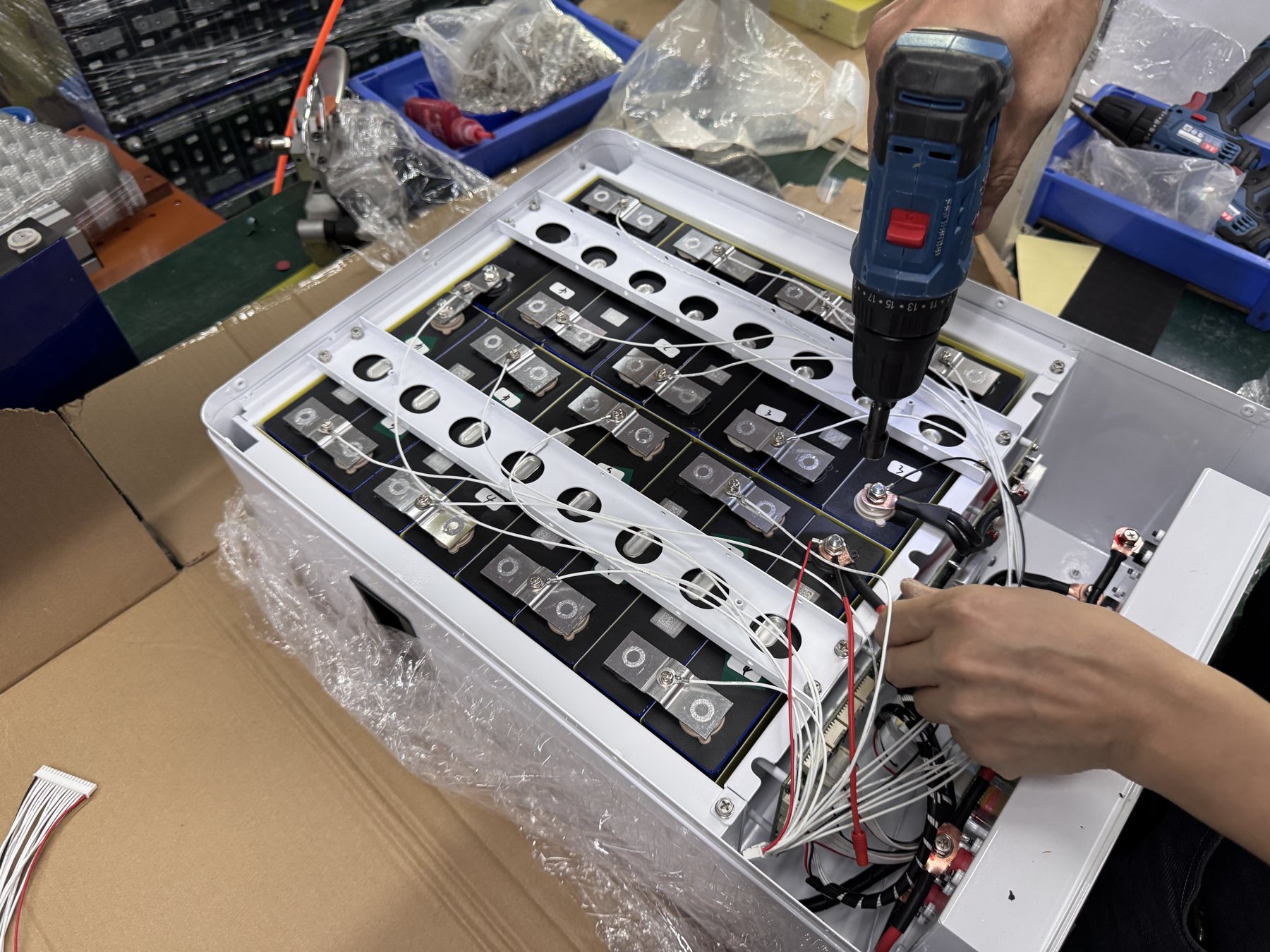
Record the site bus voltage, rectifier output behavior, charge profile, load voltage tolerance, protection scheme, cable length, and maximum continuous and transient current. Ask how the proposed battery behaves during rectifier startup, generator transfer, a mains outage, and restoration. Where a battery shares a DC bus with other strings, the system designer must review current distribution and isolation. A connector that physically fits is not proof that the whole DC architecture is approved.
The integrator should request an electrical single-line diagram showing the battery, disconnect, protective device, busbar, rectifier, load, and monitoring points. Compare terminal polarity, conductor rating, torque instructions, grounding or bonding scheme, and service isolation against the approved manuals. Field work on energized equipment must follow the site’s qualified-personnel and safety procedures. The article's checklist is a design and purchasing aid, not an instruction to make live connections.
Test the expected event sequence. If the rectifier is removed, what powers the telecom load and how is the change visible in logs? If the BMS opens a contactor or limits discharge, what does the load experience? If power returns with the battery deeply discharged, will the rectifier's recovery behavior remain inside approved limits? Acceptance criteria should describe observable voltage, current, alarm, and state transitions for the exact host and battery combination.
Decide how the BMS and site controller communicate
A BMS may provide CAN, RS485, dry contacts, local display, or another interface, but the presence of a port does not prove that it speaks the site controller's expected protocol. Ask for a protocol document with message definitions, addressing, data scaling, update rate, fault codes, and firmware revisions. Identify which device owns charge control and which signals are advisory. The interface matrix should include normal operation, warnings, protective trips, communication loss, and restoration.
For a remote site, alarm semantics are as important as electrical compatibility. Decide which events must trigger an operator action: low reserve, abnormal temperature, communication loss, protection event, fan failure, or cabinet door opening. Define severity, expected acknowledgement, and where the event is logged. A vendor statement that “remote monitoring is supported” is insufficient if the network operator cannot map its alarm points into the existing operations platform.
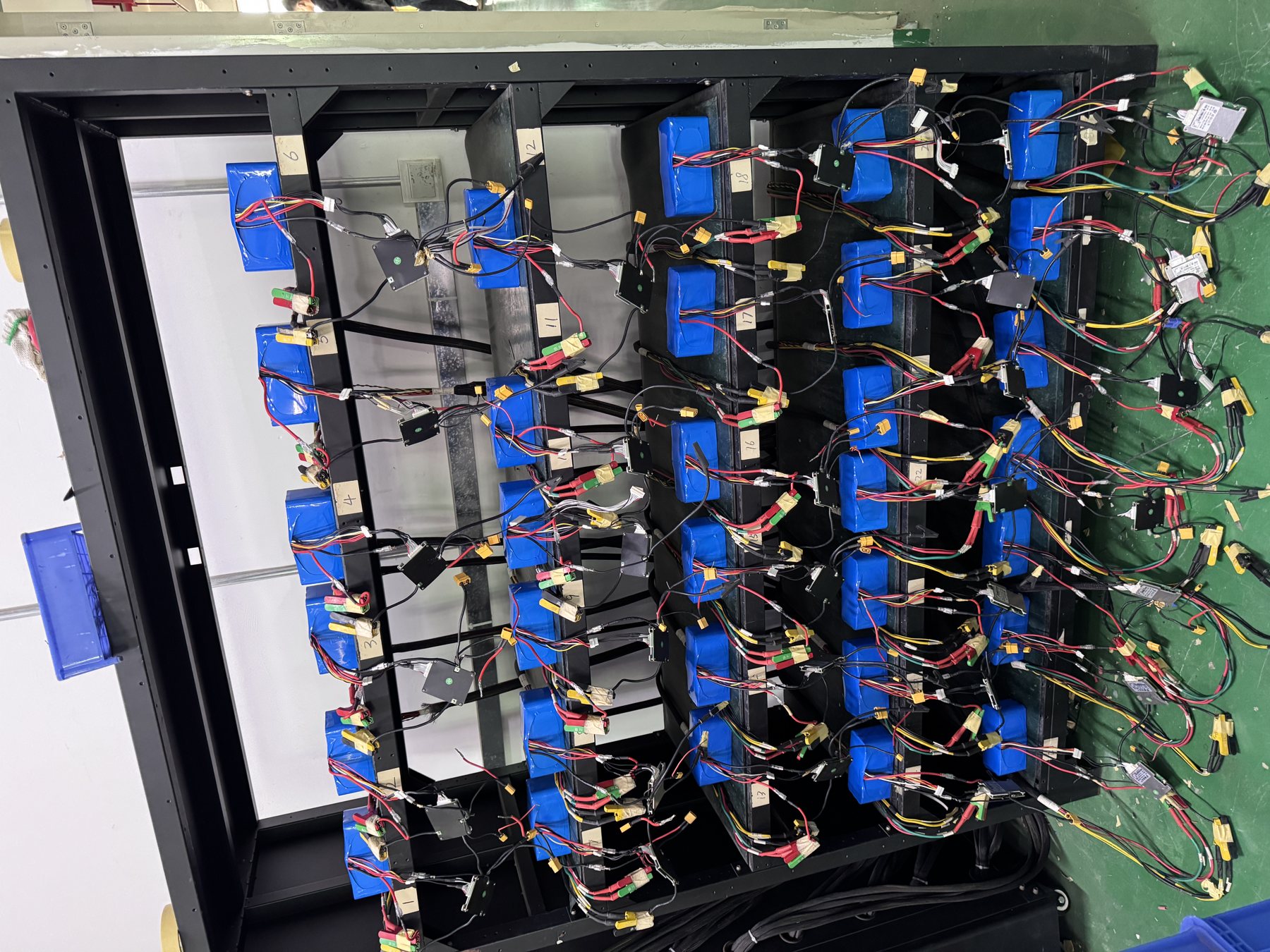
Build a bench test before broad rollout. Use a representative rectifier, controller, cable, and firmware combination. Record the message or signal seen at the controller for each intentional condition, with safe methods approved by engineering. Test loss and restoration of communications without assuming that the BMS and host fail into a safe or useful state. For a deeper interface method, see our BMS CAN and RS485 test matrix.
Plan mechanical installation and service access
Check dimensions with the cable and connector envelope included. A battery may fit on a shelf when the door is open yet leave too little room for the required bend radius, disconnect handle, or maintenance tool. Request front, rear, and side drawings with mounting-hole locations, center of gravity, mass, lifting points, and service clearances. Review the cabinet's load rating and site access route, including the ability to move a replacement unit safely.
Service access affects uptime. Can a technician read the label and serial number without removing the pack? Is the disconnect reachable before a cable is loosened? Can a failed unit be replaced while adjacent equipment remains in its approved state? Ask the supplier and integrator to rehearse a replacement on the proposed cabinet layout. A packed cabinet can be efficient at installation time and expensive to service later.
Cable routing should separate power and communication according to the approved design, protect against sharp edges, and leave enough slack for permitted service movement without pulling terminals. Record gland positions, drip loops where relevant, and the final strain-relief method. If the cabinet design is customized, freeze a drawing revision before pilot procurement. The broader OEM/ODM process is the right place to discuss enclosure and connector changes that require supplier engineering.
Write acceptance criteria for the pilot site
A pilot should prove the interface at a representative location, not merely show that the battery turns on. Before installation, agree on the site conditions, battery and cabinet revisions, rectifier and controller firmware, monitoring map, and test procedure. Define what will be measured during normal load, outage simulation, recharge, alarm events, and thermal observation. Record instrument type and measurement location so results can be compared to the engineering model.
Set acceptance criteria based on approved product and site requirements. Do not use an arbitrary universal pass number for cabinet temperature, runtime, voltage deviation, or alarm delay. A result can be acceptable for one site and unacceptable for another with a different autonomy target or maintenance access. If a test cannot safely be run in the field, agree on an equivalent bench or factory demonstration and record the remaining site risk.
After the trial, preserve photographs of the final installation, as-built wiring, BMS and controller logs, temperature observations, and any deviation from the approved design. Review exceptions before ordering a fleet rollout. A successful single site is evidence for that configuration; it should not be treated as blanket proof for every climate, cabinet model, or network controller.
Prepare maintenance and fault escalation before rollout
An outdoor backup system needs a maintenance owner. Define inspection frequency according to the site risk and approved manuals, and state what personnel will look for: blocked vents, water paths, corrosion, loose or damaged cabling, label legibility, alarm history, and unusual temperature behavior. The frequency and work method should come from the approved operating plan, not from a generic blog schedule. Remote monitoring reduces unnecessary travel but does not eliminate physical inspection.
Create a fault record that includes site ID, battery and controller revisions, serial number, timestamp, environmental conditions, power state, BMS data, rectifier data, and photographs where safe. Preserve the original event sequence. If an alarm occurred during a grid outage or maintenance intervention, that context can distinguish a battery issue from a site integration issue. For claim triage, our warranty evidence guide explains what to capture before assigning responsibility.
Safety events require immediate site procedures. If personnel observe smoke, leakage, swelling, unusual odor, or uncontrolled heating, they should follow the approved emergency plan and keep unqualified staff away. Do not tell a remote technician to open a pack or bypass protection to keep a site online. The engineering and support teams need evidence, but safety and site isolation come first.
Compare proposals against the same envelope
Ask every candidate supplier to respond to the same site sheet, electrical drawing, communication matrix, and pilot acceptance plan. A lower-priced proposal that excludes cabinet thermal work, protocol mapping, or environmental evidence is not directly comparable with a complete proposal. Mark each requirement supported, conditional, excluded, or awaiting evidence. Identify who pays for a cabinet change, firmware work, test fixture, and field visit.
Request model-specific documents rather than a general company presentation. Relevant materials may include the pack drawing, operating limits, BMS interface document, handling instructions, applicable test evidence, and a revision-controlled sample plan. Where a certificate or test report is requested, compare its named entity and model with the proposed unit. Do not infer broad certification from a single image or from a different model’s report.
Turn unresolved questions into quotation assumptions. A supplier may reasonably say that a site survey or controller protocol is needed before finalizing an enclosure or firmware scope. That is more useful than an unconditional compatibility promise. Compare total approved scope, remaining engineering risk, support responsibility, and timing before selecting a pilot supplier.
Common mistakes in outdoor battery procurement
The most common mistake is defining the requirement as “48V outdoor battery” and asking for price only. That phrase does not specify cabinet temperature, weather exposure, autonomy, recharge time, controller protocol, or service layout. Another mistake is relying on a component ingress rating to qualify the entire installed cabinet. Cable entries, doors, ventilation and field changes can alter the system boundary. A third mistake is using one successful bench demonstration as proof that an exposed rooftop installation will behave the same way during a hot afternoon.
A practical correction is to make every claim testable. Instead of “works in extreme weather,” request a model-specific operating envelope and a site temperature assessment. Instead of “compatible with our rectifier,” request a bench test using the exact host and firmware. Instead of “easy maintenance,” require an access drawing and a replacement rehearsal. Such questions improve quotations because suppliers can identify conditional work before a fleet commitment.
FAQ
Can a battery with an enclosure rating be installed in any outdoor cabinet?
No. The rating belongs to a defined item and test scope. The installed system includes cable entries, ventilation, doors, mounting and maintenance changes. Compare the exact evidence with the exposure at the site and have the cabinet designer review the assembled boundary. An advertised rating is a starting point for engineering, not a universal siting approval.
What temperature should the RFQ specify?
State the expected ambient profile and the estimated or measured temperature at the battery location, including duration of extremes and solar loading. Ask the supplier for the proposed model's operating and storage limits and for its behavior when those limits are reached. If the site profile is uncertain, include a survey or pilot measurement as an RFQ condition rather than inventing a single design temperature.
Is nominal voltage enough to establish rectifier compatibility?
No. Review the charge profile, bus window, current limits, protection response, startup behavior, recovery after an outage and communication expectations. Test the exact battery, rectifier and firmware combination against written acceptance criteria. The nominal voltage is only one descriptor of the interface.
How much pilot evidence is enough for fleet rollout?
The answer depends on variation across climates, cabinets, controllers and load patterns. Use a representative pilot to validate a defined configuration, then map each proposed rollout site against that configuration. Where a site differs materially, require additional engineering review or a second pilot. Preserve measured data and exceptions rather than declaring that one good result proves every deployment.
What should a buyer send YZL POWER first?
Send the site sheet, cabinet drawing, DC single-line diagram, rectifier and controller models with firmware, load profile, required backup behavior, environmental conditions, quantity, destination, and desired pilot schedule. Mark unknowns explicitly. That information enables a focused product and engineering discussion without implying that an unreviewed catalogue model will meet every site requirement.
Conclusion and next action
The purchase decision becomes clearer when the integrator treats the outdoor cabinet, battery, power system and monitoring network as one installation. Define the environment and interfaces, request model-specific evidence, test a representative system, and close exceptions before fleet rollout. YZL POWER's telecom and backup product directions and engineering process provide starting points. To discuss a real site, email [email protected] with the site sheet and interface drawing; the project team can review the proposed battery direction against the stated requirements.