A custom battery pack is not mechanically approved because its nominal dimensions fit inside an equipment bay. Before tooling, sample release or volume purchase, the equipment manufacturer and pack supplier need a controlled interface drawing that covers the enclosure, mounting, load path, connector orientation, cable access, environmental exposure, service removal and inspection points. This article offers a general buyer and engineering workflow. It does not specify a universal tolerance, ingress rating, vibration qualification or safe mounting method. Final limits belong to the approved design, exact model, application and relevant tests.
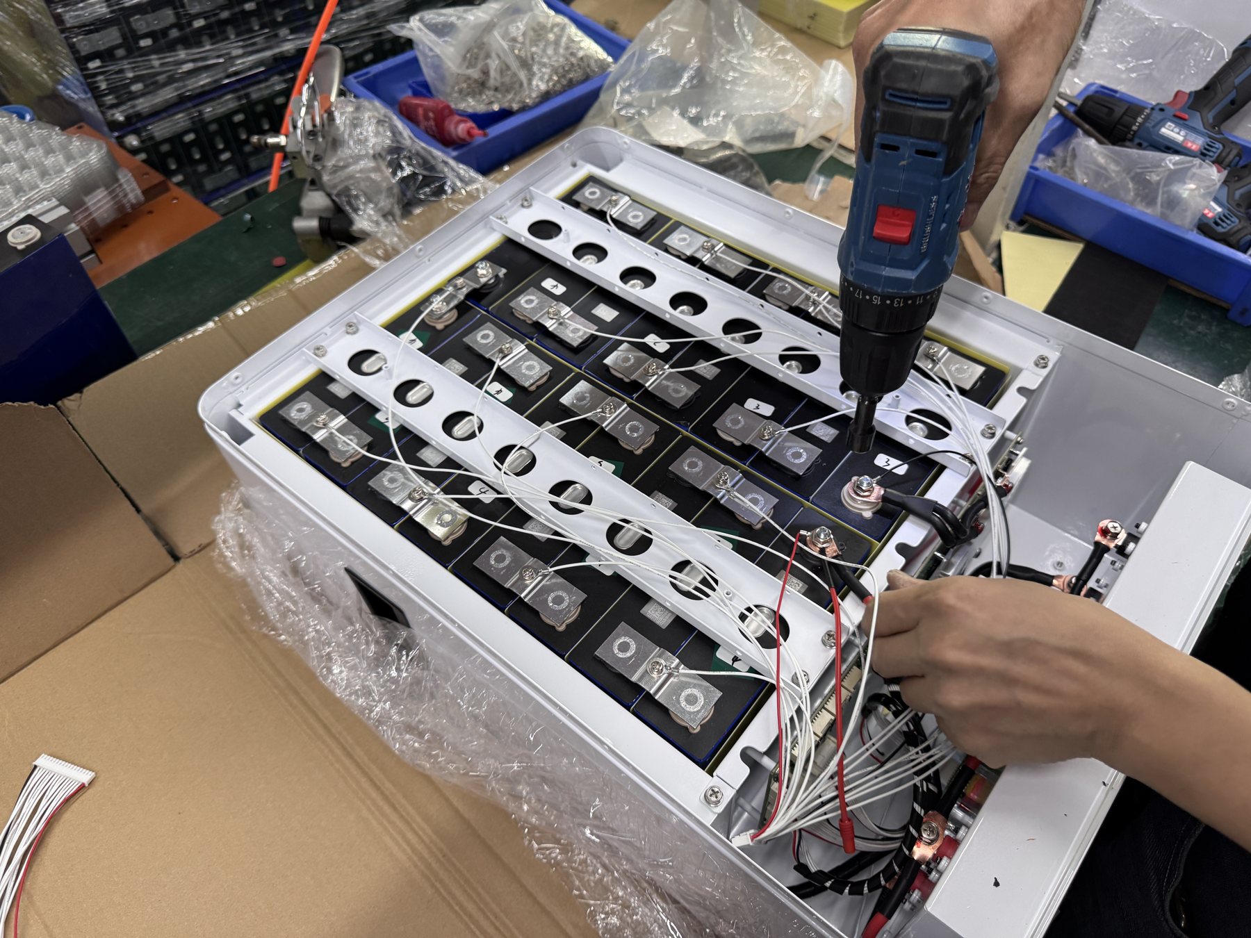
Start with the equipment interface, not a battery catalog outline
OEM and ODM buyers often send a compartment length, width and height and ask whether a pack can be made to fit. That is a useful first constraint, but it is not a complete mechanical input. A usable design must also enter the compartment, be supported in operation, connect without stressed cables, stay accessible for maintenance and survive the equipment's operating environment. The opening through which a pack is installed may be smaller than the internal volume. A door, rail, handle, nearby harness or moving part may consume the clearance that looked available in a simplified drawing.
Create an interface control document with the equipment revision and intended battery configuration. It should identify the mechanical boundary, all fixed obstacles, the permitted insertion direction, mounting features, connector keep-out area, lifting or handling points, service path and environmental assumptions. Use a common coordinate reference. Mark dimensions as measured, design nominal or still to be confirmed. Photographs help reveal context, but they do not replace a dimensioned drawing. If the original equipment has several variants, list them; a pack that fits one chassis revision should not automatically be approved for all.
The design goal needs a priority order. If the equipment cannot change, the pack may need to work within a fixed envelope, possibly affecting cell arrangement, energy, current or serviceability. If energy and power targets are fixed, the machine may need a revised compartment. Buyers should decide which constraints are hard and which can change before asking suppliers to optimize a drawing. That decision is a joint electrical, mechanical, safety and commercial trade, not simply a packaging exercise.
Define the physical envelope in three dimensions
Start with the maximum available space and the actual insertion route. Measure the narrowest opening, not only the largest cavity. Include the path of rotation or tilt needed to move the battery into position. The mounting surface, rail, frame and fasteners all need representation. Record door sweep, hinge location, latch travel and nearby service panels. If the pack must be removed without dismantling the machine, verify the complete removal trajectory with a representative model or CAD check. A design that can be installed once with the machine unfinished may be impossible to service later.
Distinguish the bare enclosure dimensions from the occupied envelope. Connectors, cable glands, terminal covers, handles, feet, labels, brackets and protective boots can project beyond the case. Cable bend and strain relief require space after mating. A terminal that technically remains within the compartment may be unreachable by a technician. Mark the keep-out zones in the interface drawing. Do not let the battery supplier infer these from a low-resolution photograph; the OEM owns the machine-level constraints.
Specify datum and tolerance strategy
A drawing needs a stable reference for dimensions. Pick mounting or locating surfaces that can be inspected on both the battery and equipment. Then identify which features control fit, which control connector alignment and which are cosmetic. Tolerances should be allocated by the engineering team based on the actual manufacturing processes and clearance stack-up. A single tight tolerance on every dimension raises cost without ensuring that the two critical interfaces align. Conversely, nominal-only drawings leave room for a sample to fit while production units interfere.
Review the full tolerance chain: machine frame, rails, brackets, fasteners, pack enclosure, connector position and cable assembly. Ask what happens at worst-case material conditions, not only at the nominal CAD model. If the equipment has welded or formed structures, compare the design drawing with measured production units. A sample taken from one machine may not represent the distribution of the fleet. The acceptance plan should state the measurement method, datums and instruments so supplier and OEM can interpret the same results.
Account for mass and the load path
The battery's weight is carried through brackets, rails, shelves or floor features into the equipment structure. Confirm the intended support points and orientation, not just the package footprint. The design owner should assess static load, handling load and relevant dynamic load from the equipment's motion or transport. A battery mounted in a stationary cabinet has different conditions from one on a mobile machine. Avoid treating an enclosure wall as a structural mount unless the approved design says it is. Define fastener type, retention method and inspection access through the responsible engineer.
Lifting and human handling deserve separate review. Can a technician move the pack using approved handles or a lifting aid without gripping terminals or cables? Is there room to place the tool and maintain control of the load during removal? If the machine is installed at height or in a narrow aisle, the service route may need a different pack split or mounting concept. The supplier should not claim a pack is "easy to replace" unless the specific equipment and procedure have been evaluated.
Treat connectors and harnesses as mechanical interfaces
Electrical compatibility discussions often focus on voltage, current and communication. Mechanical fit can fail at the connector. Record connector family, keying, orientation, mating direction, latch access, pin assignment, sealing arrangement and cable exit. Identify any protective cover that must be opened during service. If the connector is changed after a sample test, repeat the interface review. A replacement part that has the same nominal electrical rating may have a different latch or occupied volume.
Make a harness drawing that includes length, routing, support points, bend zones and strain relief. Inspect the path with the battery installed and the machine in normal operation. A cable should not be forced against a sharp edge or movable component to close a door. Separate power and communication routing when the approved design requires it. The electrical and mechanical teams should jointly confirm that service personnel can disconnect the pack in the planned sequence. An accessible connector may still be unsafe to handle without the required isolation procedure; the exact instructions belong in the approved manual.
Communication wiring also needs room for termination, labels and troubleshooting access. If the equipment uses CAN, RS485, UART or a custom interface, the drawing should capture the physical port and harness revision alongside the protocol documentation. Our BMS interface test matrix covers the signal behavior. The mechanical document must identify where that tested interface actually lands in the machine. A working bench harness does not prove that the final production harness is routed, shielded or retained correctly.
Describe the environment at the battery location
"Indoor use" or "industrial use" is too broad to determine enclosure and mounting choices. Describe the real location: temperature range at the battery, exposure to dust or water, cleaning practices, vibration, shock, nearby heat sources, sunlight, air movement and storage conditions. Distinguish normal operation from transport, washdown and maintenance. If a pack is placed inside another sealed cabinet, the combined thermal behavior may differ from the battery's standalone conditions. Engineering should review the entire enclosure system.
For temperature, identify where the measurement is taken and during which duty cycle. The ambient value outside a machine may not match the air around cells or the charger. A hot motor or inverter can warm one side of the compartment. Low temperature can affect charging strategy and may change required controls. The exact allowable charge, discharge and storage limits are model-specific. A marketing claim of high- or low-temperature suitability is not a substitute for a test report covering the proposed configuration and use conditions.
For ingress and cleaning, ask what the equipment actually encounters. A pack inside a protected indoor enclosure may need a different boundary from a pack exposed to spray, condensation or outdoor dust. Define the requested protection requirement and how it will be verified for the assembled product, including connectors and cable exits. Do not carry an IP claim from a different enclosure or sample revision into a new design without evidence. If an external cabinet supplies the environmental barrier, document the responsibilities of the cabinet and battery separately.
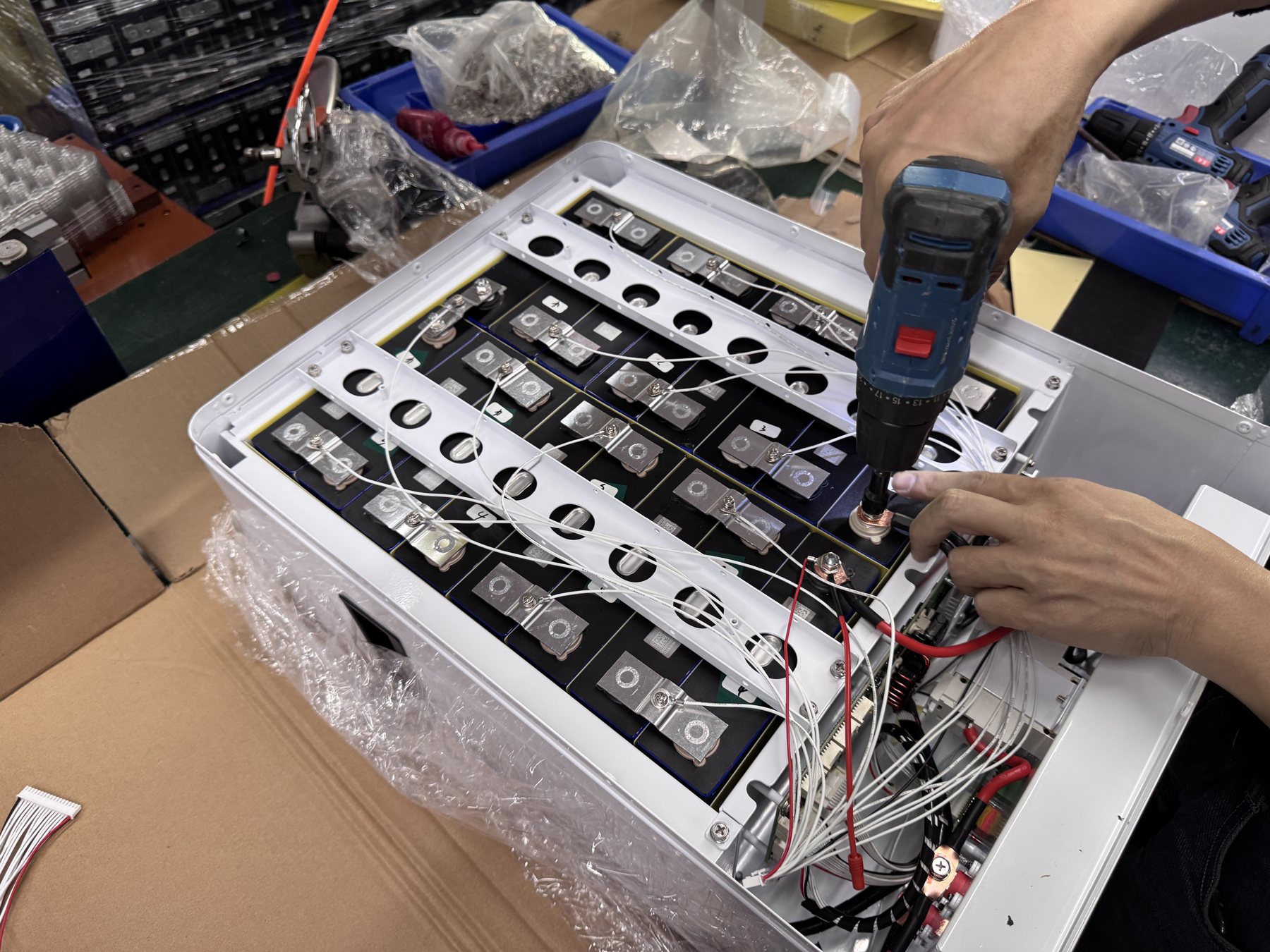
Design for inspection, replacement and fault response
A pack that fits and functions at first installation still needs a service plan. Decide which labels, status indicators, disconnects, fuses or ports must be visible when the equipment is assembled. Provide space for the specified inspection or measurement task without exposing an untrained person to energized parts. A battery may need to be removed for repair; define the isolation, access and lifting concept before fixing the enclosure geometry. The actual procedure must be written and approved by the responsible product and equipment teams.
Consider how an abnormal event will be observed and reported. The design should allow identification of the installed pack and collection of relevant BMS or host logs without improvising a field workaround. If the interface hides the serial label after installation, record the number in an accessible asset register. If a failed pack can only be removed after removing other critical assemblies, estimate service time and risk early. These are design decisions that affect total ownership cost even when they do not change the purchase price.
After-sales evidence should be aligned with the mechanical design. A photograph of the installed battery, connector, cable support and compartment condition can help distinguish manufacturing, installation and environmental issues. Do not assume a visible mark proves root cause. Combine it with serial, operating logs and event history. The battery warranty claim evidence guide describes a broader support workflow. The contract and approved support procedure determine remedies; the mechanical design should make evidence collection possible.
Use a controlled drawing and sample sequence
The OEM should issue a requirements baseline, even if some fields are marked open. The supplier should respond with a concept drawing that shows the proposed pack, critical interface dimensions, connectors, mass estimate or confirmed value, mounting approach and assumptions. Both parties should hold an interface review before prototype release. Record each unresolved item with an owner and target decision date. A drawing marked "for discussion" should not be treated as a production release simply because a purchase order is urgent.
The first physical sample is a test article. Check the actual equipment variants that matter, not only a bench fixture. Inspect insertion, mounting, fastener access, cable mating, door closure, service removal and visible labels. Record measured clearances and any temporary modifications. If a shim, hand-filed bracket or rerouted harness is needed to make a sample fit, the result is a deviation, not acceptance. Decide whether to change the pack, machine, harness or installation method and issue a new revision. Use the industrial battery pilot validation framework for the wider system release after mechanical fit is resolved.
A pre-production build should confirm that the revised drawing is manufacturable and that inspection can detect the critical features. Ask for first-article measurements at the agreed datums, photographs of cable and connector placement, and a record of any concessions. If tooling is required, confirm which dimensions are tooling-controlled and what changes remain possible without new tooling. Buyers should understand the cost and lead-time consequence of late interface changes. Supplier capability should be assessed through documented process and evidence for this project, not by a generic factory claim.
Revision control protects repeat orders
Every released pack and mating equipment revision should be identifiable. The drawing package should include part number, revision, effective date, change summary, approved deviations and compatibility with previous parts. A connector relocation or enclosure bend change can make a later replacement unit incompatible even if the commercial model name stays the same. Define whether a new pack can replace old stock, whether a harness adapter is approved and how mixed inventory is labeled. Without this control, a repeat order may reproduce the latest drawing while the customer's installed machines require an earlier interface.
A change request should describe the reason, affected serial or batch ranges, electrical and mechanical impact, verification to repeat, inventory disposition and approval signatures. The degree of review depends on the change. A label layout adjustment is different from a mounting, connector or cell-configuration change. Do not assume that a change is minor solely because it does not alter nominal voltage or capacity. Physical fit, safety, service and regulatory evidence may need updating.
What to put in the OEM/ODM mechanical RFQ
Provide a dimensioned equipment envelope and at least one clear view of the insertion and service path. Include the machine part number and revision, anticipated variants, mounting datum, connector/harness details, maximum permissible mass or load-path constraints, environment, duty cycle, target electrical requirements and expected quantity. Mark unknown values as questions rather than silently omitting them. A supplier can then quote concept work, sample iterations and production parts on a scope both sides understand.
Ask the supplier to return a drawing package, mass and dimensions for the proposed revision, interface assumptions, prototype plan, evidence for requested environmental or mechanical qualification, production inspection plan, change-control route and excluded work. Separate a quotation for a conceptual custom pack from one for a validated production configuration. If the seller has not seen the machine drawing or a representative unit, a firm fit guarantee is premature. The YZL POWER OEM/ODM page outlines the project discussion, and the product directions help buyers identify the starting battery family.
For comparison, ask all candidates to quote against the same interface revision and acceptance gates. A low sample price may exclude mechanical redesign, harness tooling, environmental verification or first-article inspection. A quote with many assumptions can still be useful if those assumptions are visible. The procurement decision should compare total approved scope, risk and timing. Treat any unsupported claims about factory capacity, universal certification or existing customer deployments as open until evidence for the exact claim is provided.
Mechanical review checklist by decision gate
At the requirements gate, confirm the equipment version, installed space, insertion path, hard constraints, electrical duty and environment. At the concept gate, check datums, maximum occupied envelope, mounting, connector keep-out, mass support and service route. At the sample gate, inspect a physical pack in representative equipment, record clearances and resolve deviations. At the production gate, verify drawing release, first-article dimensions, harness revision, inspection criteria and traceability. At the handover gate, archive as-built drawings and an approved replacement procedure.
Assign a named decision owner to each gate. The equipment OEM owns the machine boundary and intended use. The pack supplier owns the pack design and manufacturing evidence. The system integrator may own installation and functional validation. One person can hold multiple roles in a small project, but the responsibility should still be explicit. This is a general project-management pattern; it does not replace contractual allocations or local legal duties. A written gate record protects both parties from an assumption being mistaken for an approval.
Stop conditions worth writing down
Pause the release when a sample interferes with a moving part, connector latch cannot be reached, cable is strained at normal service position, mounting loads have no approved path, environmental assumptions differ from the site, or a revision change has no compatibility decision. Also pause if the measured production envelope differs materially from the drawing or required inspection cannot be performed. The correct action may be redesign, an equipment change, a different battery architecture or additional testing. Workarounds should be reviewed and documented rather than adopted silently on the line.
Avoid designing only for the first installation. Ask a technician to simulate the planned replacement after the rest of the equipment is assembled. Check whether the needed tools, gloves, lifting aid and temporary storage space can be used. A pack that is difficult to remove may increase downtime, encourage unsafe shortcuts or make future inspection impossible. This exercise often reveals issues earlier than a drawing review alone.
Frequently asked questions
Is a battery drawing with length, width and height enough for tooling?
Usually not. Tooling and release decisions also need datums, tolerances, mounting features, occupied connector envelope, insertion and service paths, mass support and environmental requirements. The required level of detail depends on the design and manufacturing process, but the mating interface must be unambiguous.
Can the supplier choose the connector after the battery sample works?
Only through controlled engineering change. The new connector may alter keying, pinout, latch access, sealing, harness routing and occupied space. Repeat the relevant electrical and mechanical checks and update both sides' drawings before production.
How can we prove fit across multiple machine variants?
List the variants and the dimensions or features that differ. Use CAD and physical checks on representative worst-case units according to the engineering plan. Record what was inspected and what remains outside the evidence. One successful installation in one prototype does not cover all variants.
Should ingress and vibration claims be copied from a similar pack?
No. Ask for evidence that applies to the exact enclosure, connectors, mounting and test conditions proposed. The equipment-level environment also matters. If the request is still a target rather than a verified result, mark it that way in the RFQ and plan the needed verification.
What if the pack fits but cannot be removed for service?
Treat that as an interface failure if replacement or inspection is part of the intended operating model. Review the service sequence and redesign the pack, bracket, harness or equipment access. Do not convert a hidden maintenance problem into an undocumented customer responsibility.
Conclusion: release a shared interface, then release the pack
A custom battery project becomes repeatable when the OEM and supplier agree on the real mechanical boundary and preserve that decision through samples, tests, tooling and later changes. The useful deliverable is an approved interface package, not simply a case that looked small enough on a quotation. Send a current equipment drawing, photos, duty profile, environmental conditions and expected volume to [email protected]. YZL POWER can discuss a project-specific pack direction and the evidence required before sample or production release.