Adding battery modules to an existing energy storage rack is a system change, not a simple increase in amp-hours. The safe purchasing decision starts with the installed battery identity, bus architecture, inverter or power conversion system, BMS communication, protection scheme, enclosure and operating profile. Ask the system designer and battery supplier to approve a specific expansion configuration, including exact model and revision, before ordering or connecting new modules. This guide is a general engineering and procurement workflow for integrators. It does not authorize a particular series or parallel arrangement, electrical work or live commissioning. The approved manuals, drawings, site rules and qualified personnel govern the actual installation.

Why a nominal voltage match is not an expansion approval
A proposal may say that two modules are both "51.2V LiFePO4" and therefore suitable for the same rack. That label leaves out the permissible operating window, internal cell configuration, BMS limits, firmware, communication roles, contactor behavior, precharge design, current sharing and protective devices. Two products can have the same nominal voltage and different responses when the host requests charge, stops discharge, loses communication or reports an alarm. Capacity also changes the charging and fault response of the whole system. Approval must be based on a documented system configuration, not on the voltage printed on a carton.
First decide what the word "expansion" means. Is the buyer adding identical modules to a rack with spare positions, adding a second rack to the same DC bus, replacing old modules with new ones, or connecting a new battery bank to a different inverter input? These are different projects. An identical-looking enclosure does not prove the internals, BMS configuration or qualification history are identical. Write the proposed before-and-after architecture as a one-page drawing. Mark battery groups, busbars, disconnects, fuses, cables, communication links, inverter ports and emergency isolation. If the current installation cannot be documented, the first task is an as-built survey.
Establish the current baseline
Collect the installed module nameplate, serial or batch range, hardware revision, BMS firmware and configuration, age, operating history and available test records. Record the host make, exact model, firmware, battery settings and communication profile. Ask for the latest approved single-line diagram and rack wiring drawing, then compare them with photographs taken at the site. Identify the installed number of modules and any unused rack positions. If some modules have been replaced or repaired, record those differences explicitly. An asset list without revision information is a weak baseline for a compatibility decision.
The baseline should include the real load and charging duty. A domestic backup system that cycles occasionally has a different operating pattern from a commercial installation that may cycle daily or support high transient loads. Describe the maximum expected charge and discharge power, normal daily energy throughput, intended reserve, ambient conditions and expected outages. These inputs do not produce an automatic expansion recommendation; they tell the engineering team what must be evaluated. A supplier cannot responsibly set a parallel-module limit from a nameplate photo alone.
Decide the architecture before comparing module quotations
Parallel modules share a bus, but "parallel" is not a complete electrical drawing. The number of strings, current path, cable length, protection on each branch, switching sequence and communication topology all affect behavior. Some systems have one master BMS reporting an aggregate limit. Others use module-level communication and a gateway or controller. A quotation should describe the architecture being approved, rather than promising that another rack can be added later without review. If a site needs future expansion, define that requirement at the original design stage and keep the approved revision record.
Ask the design owner for a maximum approved configuration for the exact model family and host combination. The answer should identify module count, permissible rack arrangement, connection method, firmware and settings, and any conditions on module state or age. Do not treat a maximum count printed in one brochure as applicable to every inverter, busbar or enclosure. A cabinet may have physical slots while the power electronics, protection or BMS network supports fewer modules in that application. Conversely, the host may support a larger energy bank while the existing cabinet has no safe cable or service space.
Current sharing and conductor review
When modules share current, differences in cable resistance, busbar layout and module condition can lead to uneven contribution. Engineering review should compare proposed cable lengths and cross-sections, terminal arrangements and protective-device coordination against the approved design. A neat installation photograph is insufficient evidence of equal current sharing. Commissioning records should show measured current or relevant BMS data across a controlled operating range, with the equipment and measurement method noted. The acceptable difference is product and system specific, so the article does not give a universal percentage.
Also review the peak and fault cases. A system may run normally at modest power yet expose a weak branch during start-up, inverter surge, charging transition or fault isolation. Confirm that no branch, connector or protective component is expected to carry more than its approved limit after expansion. The designer must assess prospective fault current, isolation and coordination for the complete arrangement. Do not move a fuse or select a larger breaker solely to accommodate an additional module. That can change the protection of existing conductors and battery branches.
State of charge, age and configuration differences
Before bringing a new module into an existing bank, ask the manufacturer for the approved matching and connection procedure. Open-circuit voltage alone may not describe state of charge accurately, and BMS displays from different revisions may not use identical estimation logic. An older module may have a different usable capacity or internal resistance from a new one. This can alter current sharing and the point at which one module reaches a limit. The engineering decision may be to add matched modules, create a separate approved bank, rebalance under a prescribed procedure or avoid mixing. None of these choices should be assumed without model-specific instructions.
A procurement team should request a written position on mixing batches, firmware revisions and aged modules. If mixing is allowed, ask for the conditions, measurements and acceptance criteria. If mixing is not supported, the commercial quote must include the cost of the approved alternative. This prevents a low initial module price from hiding a later rack replacement or controls upgrade. Record the decision in the purchase specification and commissioning pack, not only in an email thread.
Confirm BMS and host control as a system
A rack expansion changes the information the inverter or power conversion system uses to control charge and discharge. The host may read an aggregate state of charge, current limit, fault state, temperature status or contactor state from a master BMS. Adding modules may require addressing, termination, a firmware setting, a gateway change or an updated host profile. A successful initial handshake is only one test. The system must behave correctly as module availability changes and under relevant alarms and operating transitions.
Build a signal and behavior matrix before purchase. For each required value or command, record source, destination, protocol, physical port, firmware version, scaling, update behavior and safe response if data is missing. Include the host action when one module isolates itself, the communication cable is interrupted, the master changes, or charge becomes restricted. Determine whether the system continues at a reduced limit, stops safely, raises an alarm or follows another approved strategy. These are product-specific decisions. Our BMS CAN and RS485 interface matrix guide explains how to turn a protocol claim into a witnessed test plan.
A supplier statement that a module "supports CAN" or "works with many inverters" is not an approval for the installed host. Ask for the exact inverter or controller model and software version used in validation. If it differs from the customer's installation, classify compatibility as open until a controlled test or engineering review closes the gap. The relevant engineering capability page describes the project information needed for application-specific review, while the products page shows the product directions rather than a universal compatibility promise.
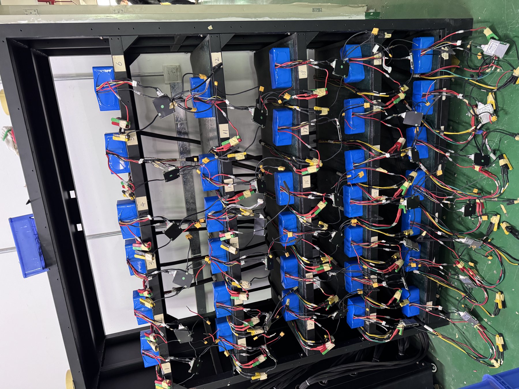
Inspect the physical rack and service environment
A rack that accepts the footprint of another enclosure still may not support its mass, cable bend radius, cooling clearance or removal path. Measure the actual site, not only the original CAD drawing. Record clear opening dimensions, shelf loading, anchor points, door swing, lifting route, overhead clearance and cable entry. Mark where a technician can isolate, inspect and replace each module. If the added modules block labels, emergency devices or airflow, a different enclosure plan is needed. The exact permitted orientation and spacing must come from the approved product instructions.
Environmental review is equally important. Compare the measured or specified temperature at the battery location with the model's approved charge, discharge and storage conditions. Check ventilation, nearby heat sources, dust, moisture, water ingress and the enclosure's protection concept. Do not assume that a battery suitable for an indoor room is suitable for an outdoor cabinet. If a cabinet is cooled, the loss-of-cooling condition belongs in the system risk review. Temperature data should identify sensor location and operating condition; a room thermostat alone may miss the microenvironment around a densely packed rack.
Expansion can increase stored energy without changing the footprint of the inverter. That may affect local design review, fire-safety arrangements, access controls, labeling, isolation and documentation obligations. Requirements vary by jurisdiction and project. The responsible designer and local authority should determine the applicable requirements for the exact installation. A marketing page or generic checklist cannot certify regulatory compliance. Procurement should request the documents and sign-offs needed in the destination market before approving a purchase order.
Define a staged verification plan
Use a gate-based approach so that assumptions are tested before shipment and again on site. The first gate is a desk review: model identity, drawings, host compatibility, protection, rack load, environment and the proposed quantity. The second is a representative integration test with the specified host and BMS revisions where the risk justifies it. The third is site readiness and receiving inspection. The fourth is qualified installation and commissioning against a signed plan. Each gate should have an owner, evidence and an explicit decision. A calendar date is not an acceptance criterion.
For a bench or pilot test, specify normal charge and discharge, expected load changes, module current sharing, communication interruption, one-module isolation, restart and recovery. Avoid destructive or improvised fault creation. Use approved controls, simulation or manufacturer-prescribed methods. Record equipment model, firmware, configuration files, measurement instruments and test conditions. A passing report should state what was actually tested and what remained out of scope. The industrial battery pilot validation guide</a provides a broader release framework for equipment programs.
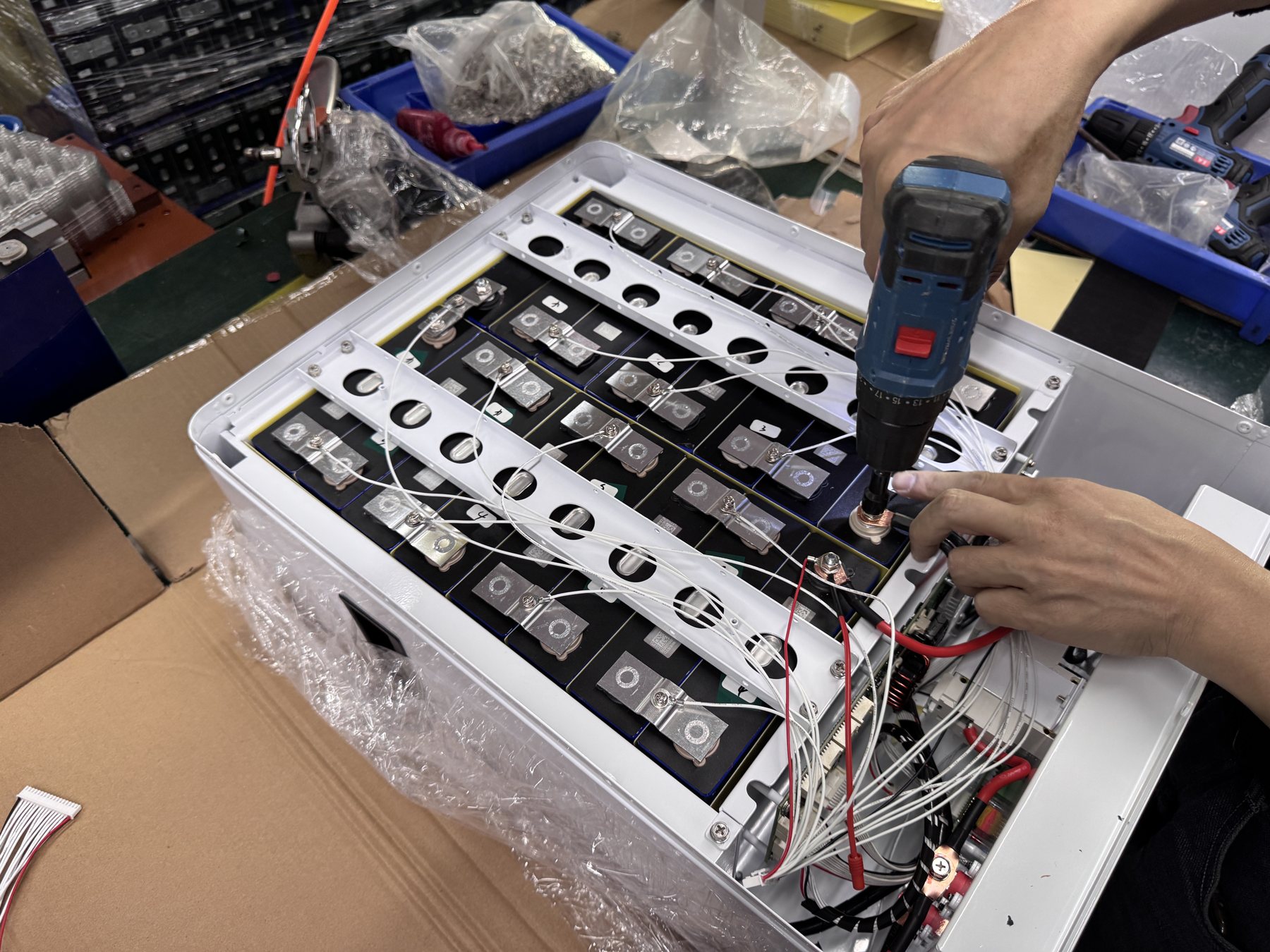
At site commissioning, confirm the physical installation matches the approved drawing before energizing. Qualified personnel should check identification, polarity, terminal hardware, protective devices, grounding or bonding where required, communication wiring and settings according to the exact manual. Capture baseline module data and host logs. Run the agreed functional checks and compare actual behavior with the test plan. If the arrangement differs from the approved revision, stop and obtain a design decision. A first start is not evidence that the expanded bank is accepted.
What the acceptance record should contain
A useful handover pack has a clear asset list and as-built diagram, product and firmware revisions, approved settings, model-specific manuals, relevant test and transport documents, commissioning results, deviations, resolved actions and operating contacts. It should also state the tested module count and any expansion restrictions. If a future service team cannot identify which pack revision was installed, it may be unable to interpret an alarm or replacement proposal. Record changes in a controlled register rather than overwriting the original design.
For ongoing operation, agree what data will be reviewed: module alarms, temperature, current distribution, state of charge trends, host power limits and significant events. The monitoring interval and acceptable ranges should follow the system's operating duty and approved design. Make sure the owner knows who receives alarms and what evidence to send. An after-sales plan is more useful when it captures serial numbers, system logs and conditions around an event than when it promises a generic response without context. See our warranty claim evidence workflow for support records after installation.
A buyer's expansion request template
Send suppliers a structured request instead of asking for "another 10 kWh" in isolation. Begin with the existing system: site location, application, installed module model and quantity, serial or batch range, age, BMS hardware and firmware, host model and firmware, current schematic and photos. Then describe the target: required energy or backup duty, expected charge and discharge profile, desired future capacity, available rack space and environmental constraints. State whether the goal is more runtime, more power, redundancy or replacement; those objectives may require different designs.
Ask the supplier to return an approved configuration drawing, exact proposed models and revisions, allowable mix with installed modules, host communication evidence, branch protection and cable requirements, rack and service clearances, test plan, commissioning instructions and open assumptions. Request model-specific documents for the destination and a clear list of exclusions. If no one can identify the installed firmware or battery configuration, price a survey or controlled sample phase instead of treating an unverified quote as final design approval.
For commercial comparison, separate module cost from engineering, hardware, controls, installation, validation and possible downtime. A lower price per kWh may be less attractive if the existing rack cannot be expanded safely or the host needs substantial changes. Compare offers on the same defined scope. Note which assumptions remain unverified and who carries the cost if they fail. This is a procurement control, not a claim that any particular supplier or chemistry guarantees a specific lifecycle cost.
Common mistakes that cause expansion projects to stall
The first mistake is to compare only nominal voltage and capacity. The second is to assume empty physical rack positions equal electrical and software capacity. The third is to omit the as-built survey and discover at installation that cable paths, protective devices or service access differ from the drawing. The fourth is to accept a broad compatibility statement without host and firmware details. The fifth is to mix old and new modules without a written rule for matching and connection. Each mistake creates a gap between what was quoted and what can be safely commissioned.
Another mistake is to move directly from a successful power-on to production acceptance. A system may appear normal while one module contributes little current, a host uses a conservative fallback limit, or a fault response has never been exercised. Conversely, a minor display discrepancy may be a configuration issue that needs investigation rather than evidence of a defective battery. Use the agreed matrix to distinguish normal behavior, unresolved observations and stop conditions. Record actual measurements and logs so the decision is repeatable.
Finally, do not let the expansion record disappear after delivery. The next service team needs the before-and-after drawing, serials, settings and test results. If an additional rack is planned later, the current approval should state whether it covers that later step or whether another review is required. An open-ended phrase such as "expandable to any size" is not a technical acceptance statement.
Frequently asked questions
Can we add a new module if it has the same nominal voltage?
Not on that fact alone. Confirm exact model and revision, BMS behavior, supported host, firmware, protection, connection topology and the approved procedure for mixing with the existing bank. The system designer and supplier should approve the specific before-and-after configuration.
Can an older rack and a new rack share one DC bus?
It depends on the approved architecture and condition of both banks. Age, internal resistance, capacity, BMS revisions and protection can matter. Request a documented engineering review and integration test where appropriate; do not infer permission from connector fit or one brochure value.
Does adding capacity always increase backup runtime?
Additional usable energy may increase runtime under an approved configuration, but the actual outcome depends on load, host limits, operating window, temperature and the condition of existing modules. A runtime target should be validated against the specified duty and site conditions. More modules do not automatically raise the inverter's power rating.
What is the minimum evidence to request before ordering?
At minimum, provide the installed model and revision, host details, a current single-line diagram, operating duty, target expansion, rack measurements and environmental conditions. Request the proposed configuration and limits in writing. If key facts are unknown, commission a survey or pilot before volume purchase.
Who should approve the final connection?
The responsible system designer, product supplier and qualified installation team should follow their defined roles under the contract and local requirements. Approval must refer to the exact model, revision, drawing and procedure. This general article is not an installation authorization.
Conclusion: buy an approved configuration, not spare modules
The strongest expansion proposal makes the future system legible before money is committed: exact modules, topology, host control, protection, enclosure, test evidence and an as-built record. Treat missing information as an explicit investigation item. For a project-specific review, send YZL POWER the installed battery and host details, current drawing, duty profile, site constraints and intended expansion to [email protected]. Our team can discuss an appropriate product direction and the evidence needed for an engineering decision; final compatibility and installation conditions require approval for the exact configuration.