A CAN or RS485 port on a battery does not prove that the battery will work with a particular inverter, UPS, charger or industrial controller. The host and BMS must agree on physical wiring, electrical settings, message structure, state transitions, limits, alarms and recovery behavior. The useful procurement deliverable is an interface matrix tied to exact hardware and firmware revisions, followed by a witnessed test in the intended system. This article shows how an OEM or system integrator can create that matrix and decide what evidence is needed before releasing an order.
This is a general engineering workflow, not a protocol specification for any YZL POWER model or third-party host. The customer materials identify CAN, RS485, UART, Modbus and customized communication as possible project directions, but no universal compatibility list is verified for publication. Request model-specific documentation and an approved integration plan. Electrical work and fault testing must be carried out by qualified people under the product and site safety instructions.
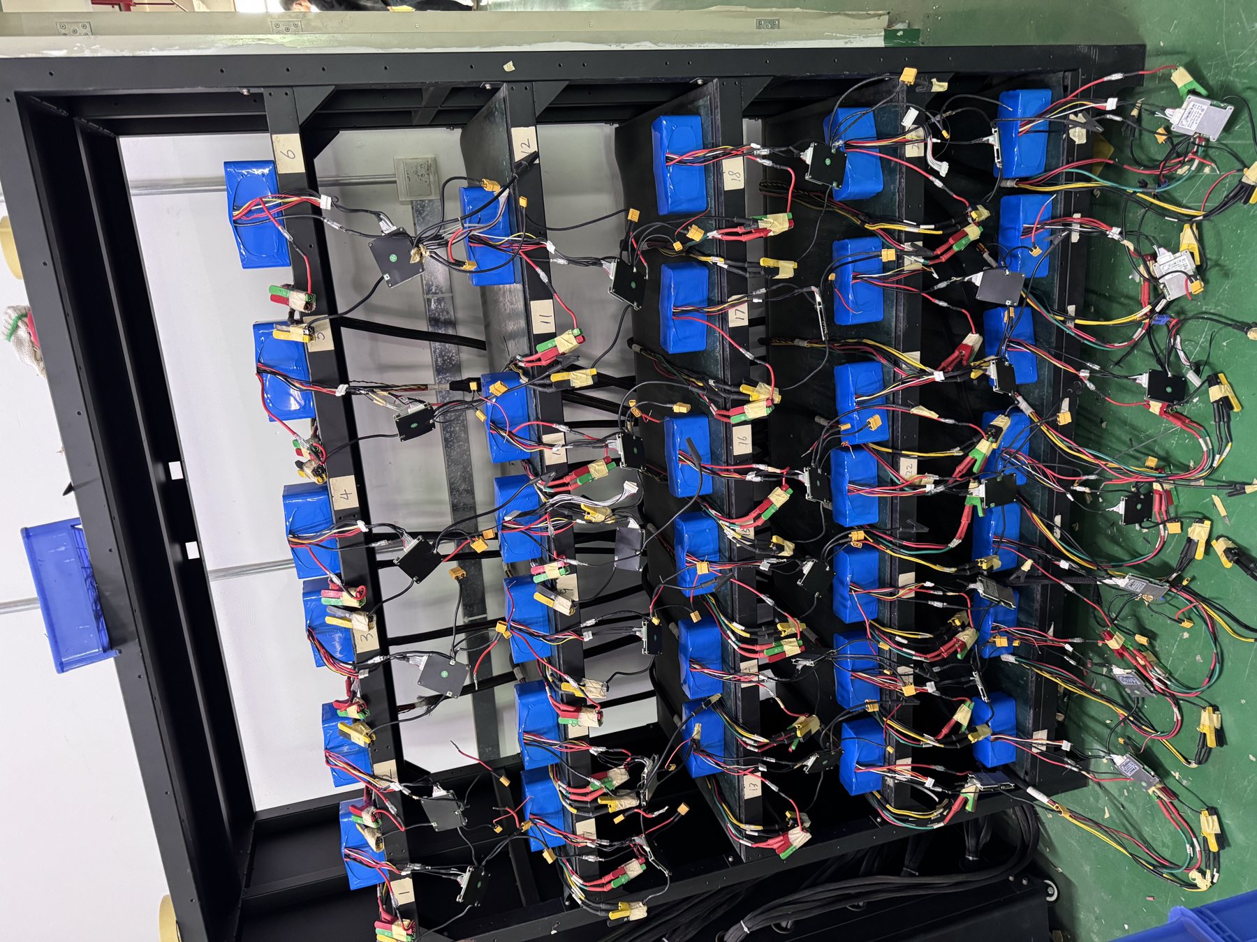
Define the system boundary before choosing messages
Begin with a system sketch that names the battery pack or rack, BMS, host controller, charger or rectifier, inverter or UPS, monitoring gateway and any cloud or building-management system. Identify which device is the source of each control decision. For example, the BMS may calculate permitted charge and discharge current while the host decides how quickly to change power. A supervisory controller may display alarms without being permitted to override protection. These roles should appear on the drawing instead of being inferred from a connector label.
List the equipment model and revision for every participant, including firmware and parameter files. A protocol that worked with one host firmware may behave differently after a vendor update. Likewise, a BMS hardware revision can change port assignment or available signals. The interface agreement should specify the exact combination being approved. If a supplier proposes a substitution, the project team can then identify which tests must be repeated.
Separate the power path from the communication path. A battery can power a DC bus while reporting no data; a host can display plausible data while the protective path is wired incorrectly. The test plan needs both tracks. It should also say what happens if the communication path fails while power remains connected. A safe design may curtail charging or discharging, switch to a defined fallback mode, or open a contactor, depending on the application. Do not make a generic assumption about which response is correct.
Create a one-page interface inventory
A useful inventory names each physical port, connector, pin assignment, shield and ground arrangement, termination requirement, device address where applicable, bus speed or serial setting, protocol name and version, and the document that defines it. Add the test tool and log format to be used. Leave unknown entries visibly open. An unfinished line is a project risk to resolve; it should not disappear into a general statement that the battery “supports CAN.”
Confirm the physical layer before decoding data
CAN and RS485 are electrical communication methods, not complete application protocols. First verify the intended connector and pinout against controlled drawings. Check polarity or line assignment, termination, cable type, shielding and routing as specified by the relevant equipment manuals. A cable assembled for one inverter family may fit another socket while carrying different signals. Do not test by swapping pins on a live system without an approved procedure.
Record the bus layout. Some hosts expect a single battery interface, others connect through a gateway or a master module. Multi-drop serial networks need addressing and a defined termination plan. Rack systems may have internal module communications that must not be confused with the external host port. The person creating the harness should have a drawing showing where each conductor lands and how the shield is handled. A photograph alone is useful evidence, but it cannot replace a pin table.
Commission the link in a safe low-power state. Confirm that the expected devices are visible, no line is shorted, the host sees the intended port and the diagnostic tool captures traffic with timestamps. Record bit rate or serial settings from the approved documents instead of trying many values until data appears. A noisy or intermittent link can produce apparently valid frames during a short demonstration and fail under normal cable routing or electromagnetic conditions. Include a longer observation under the installed configuration.
Map meaning, units and ownership for every signal
A message map should include frame or register identifier, source device, destination or intended subscriber, update rate, data length, byte order, scaling, unit, valid range, invalid-value convention and behavior when stale. A raw number without its unit is not a useful integration contract. Battery voltage, pack current, state of charge and state of health may each be represented differently by different vendors. The host must interpret sign conventions consistently: charging current that appears positive on one side may be negative on the other.
Control values need more scrutiny than display values. A reported maximum charge current is not necessarily a fixed pack rating; it may change with state of charge, temperature or protection state. The host should know whether the value is an immediate limit, a ramp target or a diagnostic reading. The same applies to maximum discharge current and charge-voltage requests. Document which device is authoritative when values conflict. A display that shows the correct voltage does not prove that the charger follows the BMS's current limit.
Define the behavior of “unknown,” “not available” and zero. Zero could mean a real zero-current limit, a missing message or an initialization value. If the host treats a missing limit as “no limit,” a link loss can become a hazardous control failure. If it treats every brief missed frame as a permanent fault, the equipment can become unavailable unnecessarily. The approved interface should state the timeout, fallback action and restart conditions for each critical signal.
Use an interface matrix that can be signed
For every signal, add columns for requirement, supplier reference, host interpretation, test stimulus, observed frame or register, pass criterion and owner. Mark whether the signal is critical for control, important for alarm, or informative only. This classification lets the team focus testing on behavior that can affect safety or availability. It also avoids spending days polishing a dashboard field while leaving a current-limit handshake untested.
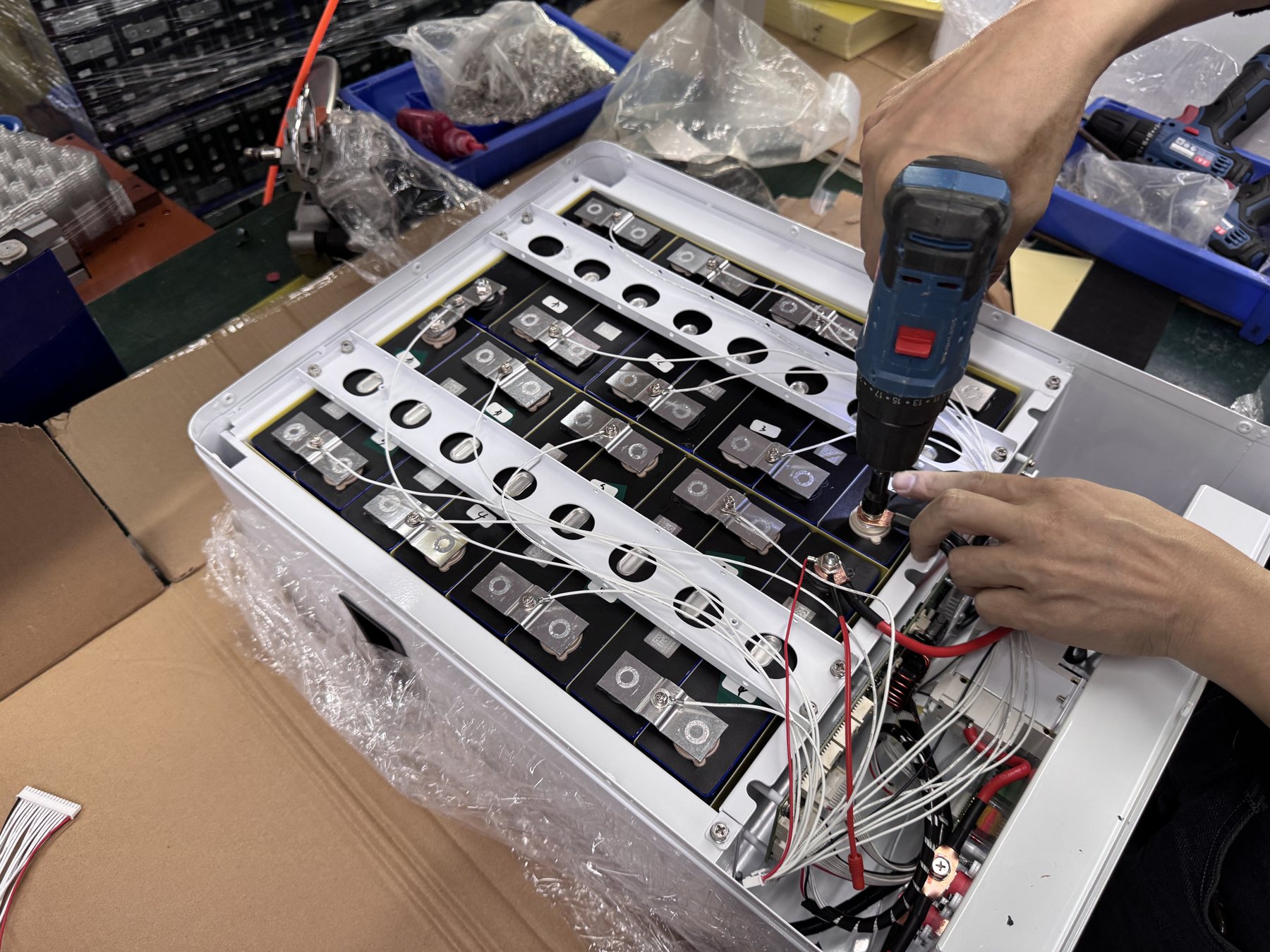
Test state transitions instead of only steady-state readings
An integration demonstration often starts with the battery already running and the host already charging. That misses the events where mismatches appear: power-up, precharge where applicable, charger enable, load enable, standby, shutdown, recovery after an alarm and reconnection after a communication interruption. Map each state and permitted transition. Identify which device sends the request, which confirms it and which can veto it. A state diagram can make disagreements visible before software is changed.
For each transition, record the expected sequence of messages and the electrical action. For example, when charging becomes permissible, the BMS may advertise a limit and the host should move its output toward the allowed condition. The exact order depends on the agreed protocol; do not copy a sequence from another product. Test both normal and refused transitions. The system should handle a host request that arrives while the battery is not ready without silently ignoring a critical condition.
Timing matters. A host may receive correct data but react too slowly to a changing limit. A BMS may publish a status at an interval the host does not expect. Define acceptable timing from the approved application specification and verify it with synchronized logs. Avoid universal millisecond claims unless they are documented for the exact product. The evidence should show timestamps on both the communication and power measurements so the team can connect a frame to a physical response.
Verify limits and alarms as system behavior
A battery's protective functions and the host's control functions should cooperate without relying on a protective trip as the normal control method. In a controlled test, check that the host respects the advertised charge and discharge limits under the operating conditions the project requires. Observe the actual current, not only the value on a screen. If the BMS reduces a limit because of temperature or state of charge, the host should respond according to the interface agreement. A hard protection event should remain a defined last line, not a routine way to regulate power.
Create an alarm table with code, meaning, severity, source, host display, remote notification, required operator response and recovery condition. Distinguish a warning that allows continued service from a fault that must stop operation. Confirm that the network management system or HMI does not silently discard a fault because it lacks a text label. A raw hex code can still be useful if the operator has a controlled codebook and dispatch rule.
Do not induce unsafe faults in the field to prove every protective function. Some behaviors require laboratory equipment, manufacturer test records or a safe simulation method. Record which evidence comes from a bench test, which comes from a model-specific report and which was observed on the installed equipment. The battery pilot validation plan provides a broader release-gate framework; this matrix narrows the focus to host-to-BMS exchange.
Design a communication-loss test with a safe fallback
A cable can be unplugged, a gateway can restart and a controller can stop publishing frames. The interface plan should state how long the system may operate on the last valid value, whether the host enters a reduced-power mode and what permits normal operation to resume. This is an engineering decision for the application, not a universal rule. A telecom backup system and a mobile industrial machine may have very different requirements for continuity and safe stopping.
Test the approved loss scenario under controlled load. Capture the last good message, the time the host recognizes loss, the resulting current or power change, the displayed alarm and the recovery sequence. If communication is restored, confirm that the host does not jump immediately to an old limit or clear a fault before the BMS reports readiness. If a gateway has a cached value, its age should be visible to the host or constrained by the protocol design.
Avoid a common false positive: a screen may continue showing a stable state of charge after the link drops, making operators think communication is healthy. Include a heartbeat or freshness check in the test matrix and verify the user interface's behavior when data is stale. A clear “data unavailable” indication is often more useful than a plausible but old number. The exact display and timeout should be agreed with the host vendor.
Control firmware and parameter revisions
When a test fails, teams often change several settings at once: host protocol profile, BMS firmware, current limit and cable termination. The next successful start then proves very little about which change mattered. Use a change log that identifies original value, new value, reason, approver, affected sample and tests to repeat. Preserve log files from the failing state. The interface matrix should point to the exact firmware and parameter files used for every pass result.
Treat a supplier's “compatible with Brand X” claim as a request for detail, not a final conclusion. Ask which equipment model, firmware and protocol profile were tested, which functions were included, and whether the battery configuration matches the proposed order. A host vendor can update a protocol without changing the front-panel model name. A battery vendor can replace a BMS component without changing nominal voltage. Written version control is the practical defense against a compatibility claim aging silently.
Before volume release, build a production-intent sample with the intended harness and software image. Repeat the critical interface tests on that version. If the final production pack uses a different cable length, gateway, master module or firmware, assess whether previous evidence still applies. The OEM/ODM process should be used to agree on project inputs, controlled outputs and change approval rather than treating communication as an informal accessory.
Build a test sequence with clear acceptance gates
Begin with document review: drawing, pinout, protocol specification, host manual and approved versions. Next perform a de-energized wiring and continuity check under the safety plan. Then establish low-power communication, decode essential status, verify units and signs, and observe data freshness. Only after those gates should the team apply charging or discharge loads. Finish with state transitions, safe alarm tests, communication loss, recovery and a production-intent repeat.
For each gate, define an owner and evidence file. A screenshot can show a host display, but a bus trace may be needed to prove message content. A current trace shows whether a published limit was followed electrically. A wiring photograph helps verify the harness but needs a drawing reference and connector label. Combine the evidence so an independent engineer can reproduce the conclusion. Do not require every measurement to be perfect; require that exceptions are visible and resolved.
If a test is not possible at the supplier's bench, mark it as a field acceptance item rather than silently dropping it. The project can distinguish a conditional release for sample evaluation from approval for routine operation. The field commissioning checklist shows how the approved interface can be checked again after delivery and installation. A bench pass and an installed-system pass are complementary evidence.
A useful minimum matrix
Include these rows even if the exact protocol uses different names: identity and version, pack voltage and current, state of charge, battery ready or enable state, charge and discharge limits, temperature or derating status, warning and fault codes, contactor or output state where available, communication freshness, safe loss of link, reconnection and controlled shutdown. Add any application-specific signals, such as generator coordination or regenerative current, only when the host and battery architecture require them. Every row needs an expected host action, not just a decoded value.
Interpret a failed test before changing hardware
If the host sees no frames, begin with the physical layer: port selection, cable, pinout, power state, termination and line settings. If frames are visible but the host shows no battery, inspect protocol selection, identifiers, data length, byte order and expected startup handshake. If the host shows a battery but refuses charging, compare the BMS's published limits, host interpretation and charger state. If a protection trip appears during load, synchronize the current trace and BMS event log before blaming either device.
Intermittent faults require attention to conditions. Record cable routing, nearby switching equipment, load transitions, temperature, vibration and the exact time of failure. A single successful restart after reseating a connector does not establish a root cause. Try to reproduce the symptom under a controlled and documented change. If the test team cannot isolate the cause, describe the uncertainty in the release decision and identify the additional evidence required.
Keep safety boundaries visible. Do not bypass a fuse, defeat a BMS protection or raise a limit to make a demonstration pass without engineering approval and a revised risk assessment. A system that works only after its protection has been relaxed is not automatically compatible. Escalate the discrepancy to the owners of both interfaces and keep the original logs.
Give procurement a document it can compare
A buyer evaluating suppliers should ask for the interface matrix, supported host model and firmware list, pinout, protocol version, sample test report, known limitations, proposed change process and field-commissioning plan. A generic “CAN/RS485 supported” line is insufficient. The proposal should also state whether the host vendor must supply protocol documents, special firmware or access to a test unit. These dependencies affect schedule and cost.
Separate a verified integration from a planned integration. Verified means the named battery and host revisions were tested for a defined set of functions under recorded conditions. Planned means the parties believe integration is feasible but have open work. This distinction lets the buyer place a pilot order with a realistic acceptance gate rather than assume every requested function is already available. It also discourages an unsupported compatibility list on a public product page.
The final quote should connect the interface work to the product configuration. YZL POWER's industrial battery and backup product directions include project-specific communication possibilities, but exact support belongs in a model-specific agreement. The engineering page describes the application review path. Provide the intended host model, firmware, bus diagram and protocol files when requesting a technical review.
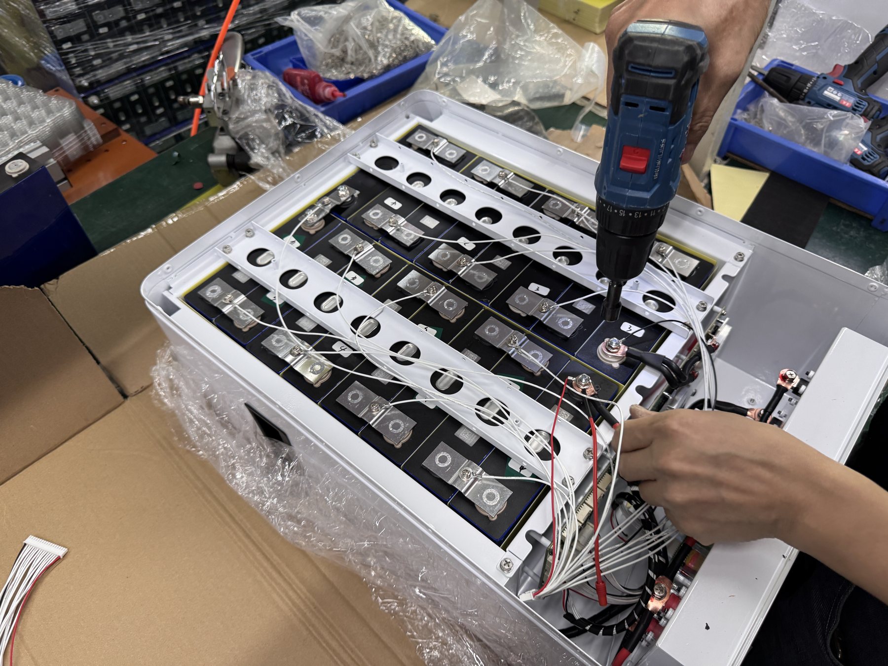
Frequent mistakes and how to avoid them
The first mistake is treating CAN or RS485 as though either were a complete, interchangeable protocol. Correct it by collecting the application-layer document and a signal matrix. The second is relying on nominal voltage and a connector photo to declare compatibility. Correct it with the operating window, host settings and controlled harness drawing. The third is testing only a happy-path power-up. Correct it with limits, alarms, link loss, recovery and shutdown cases.
A fourth mistake is looking only at the host screen. The display may show the correct voltage while the charger ignores a changing current limit. Measure the electrical response. A fifth is accepting a successful sample after undocumented firmware adjustments. Freeze the final versions and repeat the affected test. A sixth is publishing a blanket “works with all inverters” claim based on one profile. Report the exact tested combination and conditions instead.
Do not let the matrix become an unmanageable list of every possible register. Prioritize signals that affect protection, control and operator decisions. Some informational fields can be accepted with less intensive testing if the project owner agrees. The point is to make critical behavior reproducible, not to create paperwork for its own sake.
Frequently asked questions
Does a battery with a CAN port work with any CAN inverter?
No. CAN defines the communication bus, while the devices still need a compatible message format, timing, electrical connection and behavior. Obtain the exact host and battery protocol versions and verify the required functions. An adapter or gateway may be possible in some projects, but it becomes another controlled component to test.
Is RS485 the same as Modbus?
RS485 is a physical communication method. Modbus is one possible protocol that can run over a serial link, with additional details such as address, register map and data interpretation. The presence of RS485 does not prove that a device speaks the expected Modbus variant or register map. Check the exact documents.
Can the host rely on a fixed charge-current limit?
Only if the approved battery and application specification says that is valid. A BMS may change its permitted limit with operating conditions. The host needs to follow the agreed control scheme and handle stale or invalid data safely. The test matrix should include at least one controlled limit-change case when relevant.
What evidence is useful if the host stops recognizing the battery?
Provide the exact models and firmware, wiring drawing, pinout, parameter file, timestamped bus trace, BMS and host alarms, operating state and recent changes. Preserve the failing configuration before editing it. That evidence helps separate wiring, protocol and state-machine problems.
Should every possible BMS fault be created during commissioning?
No. Some fault tests are unsafe or require specialist facilities. Use approved simulations, bench tests or model-specific reports where appropriate. State what was observed directly, what was supported by documentation and what remains an open verification item.
Decision and project inquiry
A reliable BMS integration is a versioned interface agreement plus a test record. It covers physical wiring, data meaning, current limits, states, faults, loss of communication and recovery. A procurement team can then compare bids on the functions that matter to its equipment and release a configuration only after the planned gates pass. This is stronger than a broad compatibility claim and easier to maintain when firmware changes.
Send the host model and firmware, electrical diagram, protocol document, operating modes and required alarms to [email protected] or WhatsApp +86 138 0280 9405. Ask YZL POWER for a model-specific interface review, sample matrix and defined test responsibilities before a production order.