An AGV or AMR battery is suitable only when the vehicle, charger, work schedule, safety controls, and maintenance process function together. Before an OEM approves a battery pack, define the fleet's operating cycle, the time and location of charging opportunities, the peak traction and auxiliary loads, and the behavior required when a robot cannot reach a charger. Then test the proposed pack and charging interface on a representative vehicle across a full shift. A nominal voltage, amp-hour rating, and connector photograph do not prove fleet availability. This guide describes general engineering and purchasing practice; any particular YZL POWER pack capability or limit needs model-specific confirmation.
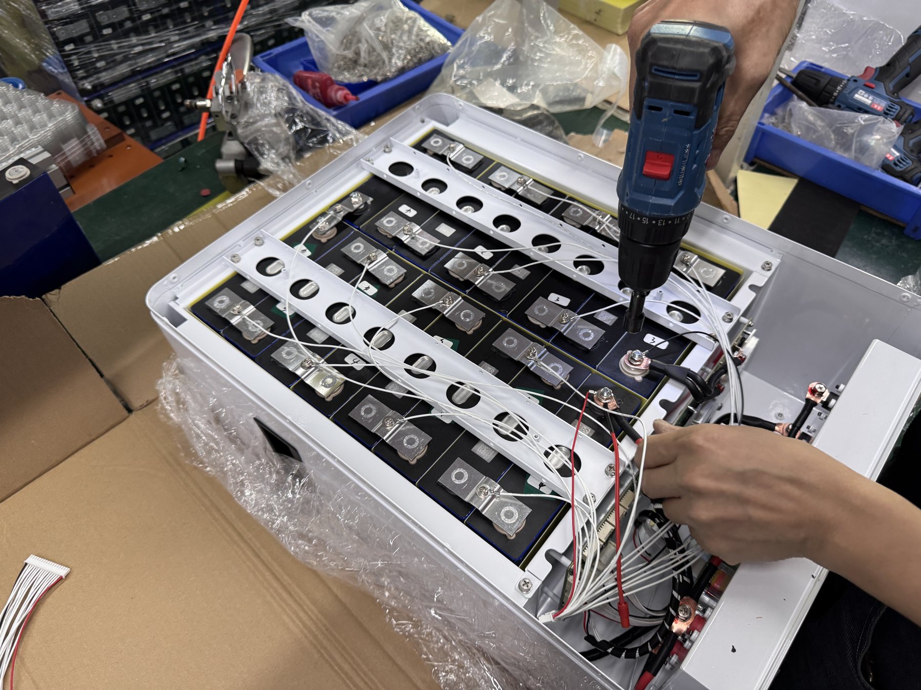
Start with the vehicle's real mission, not a battery catalog
Map what a vehicle does during a complete operating day: travel with and without payload, acceleration, lifting or conveying, waiting, wireless communications, navigation, safety stops, docking, and charging. Note the duration and sequence of each state. A duty cycle derived from an average current can miss short high-current events or a long queue at a shared charger. Ask the vehicle OEM or fleet operator for log data from a representative route when it exists. If no data exists, record the assumptions and plan an instrumented pilot.
Separate a single robot's energy budget from fleet throughput. A battery may support a vehicle for one shift under a light route while a busier lane requires frequent charging. The decision should state the required completed jobs, vehicle availability, acceptable charging interruption, and reserve for an unexpected detour or blocked dock. These are operational requirements, not battery features. A buyer should avoid comparing packs only on nominal watt-hours when the intended service level is defined in completed missions.
Identify the worst credible mission rather than averaging every vehicle together. A loaded unit climbing a ramp, a vehicle running in a hot area, or an AMR spending long periods under a powered payload attachment may have a different profile. Define which conditions the proposed pack must cover and which require a separate configuration. The goal is an evidence-backed product family, not a universal claim that one pack will fit every vehicle.
Draw the charging workflow before choosing a connector
Decide whether the fleet uses manual plug-in charging, contact-based docking, battery swapping, or another approved method. For each method, diagram the movement from a work zone to the charging point, the handshake or operator action, the active charging interval, and the return to service. Include queues and a missed dock attempt. A charger that can replenish a pack quickly in isolation may still create a bottleneck if several vehicles reach one station at the same time.
Define what triggers a charging trip. The fleet controller may use a state-of-charge threshold, an expected future task, a scheduled break, or a manual command. A displayed percentage is an estimate; the charging policy should preserve enough reserve to reach a station under the actual route and load. If a vehicle can be diverted or the charger can be busy, include that contingency. Battery procurement should not promise fleet availability without knowing how the controller makes these decisions.
Describe the physical and electrical interface together. A docking contact must align under vehicle tolerances and wear; a manual connector needs access, strain relief, and safe handling. The battery's voltage and current limits must match the charger profile. Include grounding or bonding and protective-device design according to the approved vehicle architecture. A connector's mating compatibility is only the first check.
Build a time-based energy and charging model
For each vehicle class, estimate energy consumed in travel, payload operation, idle services, and auxiliary systems. Use measurements where possible and document the sample route, payload, temperature, and software state. Add the energy needed to return to a charger and the operational reserve. This creates a target usable-energy requirement. The pack's nominal energy does not equal usable energy under every current, temperature, aging state, or BMS protection setting.
Model charging as intervals. How long is the vehicle actually connected? What current does the charger deliver after its own limits and the battery's BMS constraints? Does charging taper near the intended upper state? Is the charger shared, and what queue time is expected during peak work? A simple division of energy by charger nameplate power can be useful for an early estimate, but it cannot establish an operational schedule. A pilot must verify the curve on the proposed hardware.
Run a fleet simulation or a spreadsheet with several scenarios. In one, every vehicle follows an ordinary route; in another, a charger is unavailable; in a third, a higher proportion of heavy missions occurs. State which variables are measured and which are planning assumptions. The result should tell the buyer whether the planned number of packs, chargers, and charging windows supports the required throughput. If it does not, identify whether a larger pack, more charging points, different dispatch rules, or an approved swap process solves the constraint.
Verify current peaks and protective behavior
Traction motors, lift actuators, pumps, or other payload devices can produce brief current demands far above steady travel current. Ask the OEM for a logged peak profile with duration and repetition, not only a single maximum number. The battery supplier should compare it with model-specific continuous and transient discharge limits, connection hardware, cable ratings, thermal behavior, and BMS trip rules. A pack that passes a low-load drive test may still interrupt power during a loaded acceleration or lift.
Investigate what the vehicle does if the BMS limits or opens the discharge path. Does the robot stop in a safe condition? Can it block an aisle, drop a payload, or lose steering or communications? The vehicle's safety architecture must address these outcomes. A battery article cannot certify machine safety; the OEM and site safety team must validate the complete machine against their applicable requirements. The procurement test should nevertheless observe the interface and fault response that the OEM depends on.
Define a safe recovery procedure after a protection event. Some faults clear automatically when conditions return; others may require an approved reset or service action. Do not allow production staff to bypass the BMS, bridge a contactor, or modify wiring to move a stranded vehicle. Include a controlled removal or towing procedure in the fleet operating plan. The battery's service instructions should match the vehicle's access constraints.
Test the charger and BMS as a paired system
Request the exact charger output profile and the battery's approved charging range. Confirm start-up behavior, current limits, end-of-charge behavior, temperature response, and automatic restart after interruption. If the charger and BMS exchange data, obtain the message map and firmware revisions. “CAN supported” or “lithium charger” is not a complete compatibility statement. The BMS interface matrix provides a separate test structure for communications and fail states.
Test normal and abnormal docking states. What happens if the charging contacts touch briefly and separate? Can the vehicle drive while power contacts remain engaged? What if the charger is powered down, the communication line fails, or a vehicle docks with an active alarm? The approved architecture should prevent unsafe or confusing transitions. Record voltage, current, charger state, BMS state, and controller messages during these tests under qualified supervision.
Pay attention to charge temperature. A battery that has just completed a demanding mission may be warm, while a charger placed near a cold receiving door may see a different environment. Compare the exact pack's charging limits with the intended operating envelope. If charging is inhibited or derated, the fleet controller needs to know and to assign another vehicle. A mechanical dock can appear successful while the pack accepts little or no energy.
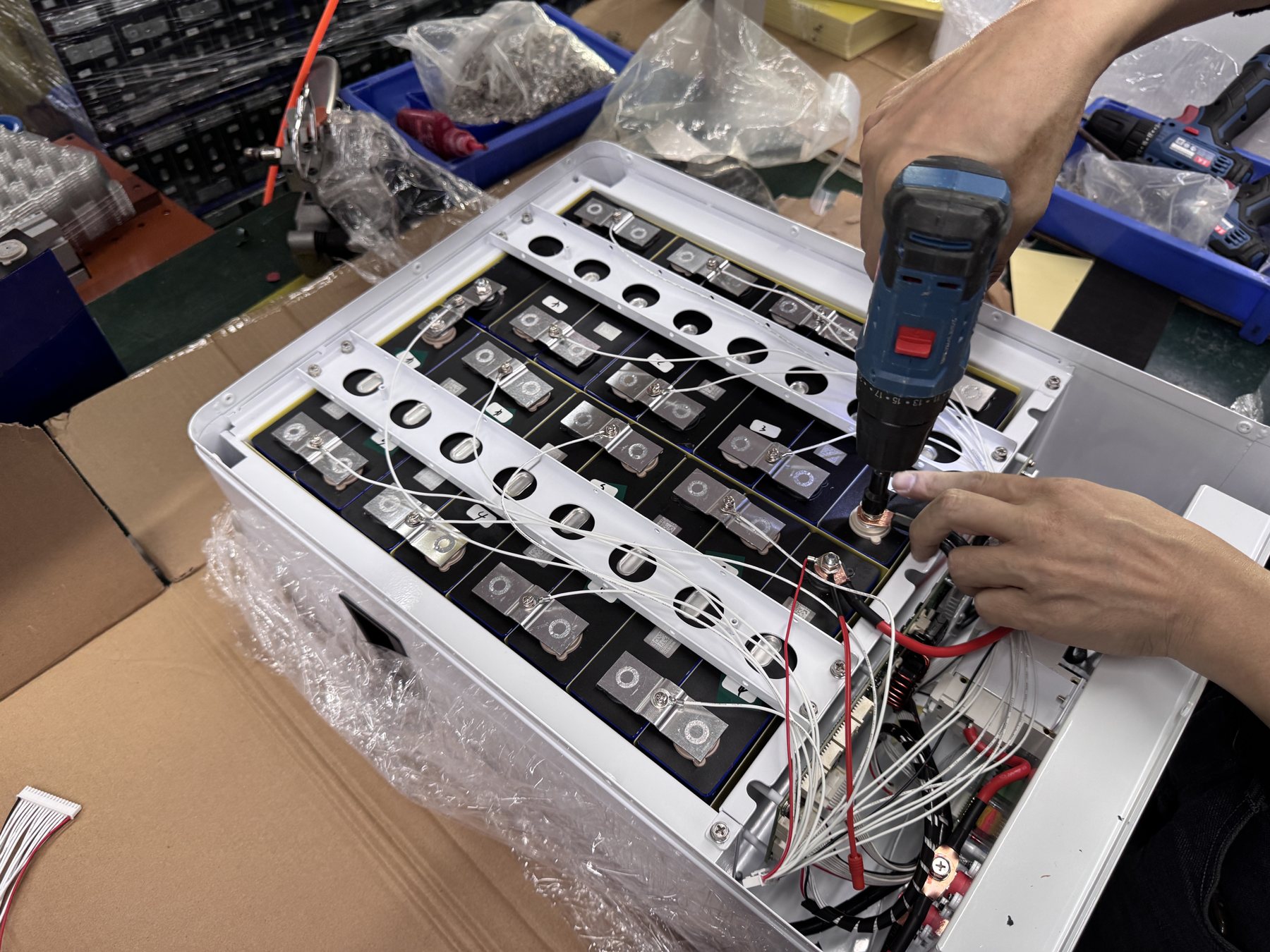
Specify the data the fleet controller actually needs
The controller may need pack voltage, current, temperature, state of charge, state of health, warnings, and charging status, but the required set depends on the fleet software. Define each variable's meaning, units, update rate, validity rules, and behavior when communications fail. A percentage without a validity flag can be worse than no value if it is stale. Require the integrator to show how the controller reacts to implausible or missing data.
Separate operator information from safety control. A dashboard can help plan charging but should not replace the vehicle's certified safety functions. Agree which faults stop a mission, which allow a controlled return to base, and which merely schedule service. For each state, document the responsible subsystem and the message shown to an operator. The battery supplier should not be asked to infer the vehicle's safety case from a list of CAN IDs.
Keep data handling maintainable. If the battery firmware or controller software changes, can the fleet still interpret alarms correctly? Store the protocol revision with the approved bill of materials and test record. Establish a change process for new vehicle software releases, alternative chargers, or spare-pack revisions. A successful sample demonstration does not automatically approve every later combination.
Review pack fit and service access inside the vehicle
Request a three-dimensional envelope including connectors, harness bends, mounting features, fasteners, and removal path. Check that the pack can be installed without trapping a power cable, obstructing ventilation, or forcing a technician to work around a sharp structural edge. The pack must be secured for the vehicle's vibration and motion environment using an approved design. A drawing showing only the outer case length, width, and height is insufficient.
Locate the center of mass and consider the effect on the vehicle's stability and payload envelope. Ask the OEM to assess ground clearance, suspension or caster loads, and accessibility during service. A heavier pack can change vehicle behavior even when it fits the compartment. Conversely, a lighter pack may change the balance that the chassis designer assumed. These are vehicle-level checks, not claims about a specific YZL POWER model.
Plan the replacement sequence. Can staff identify the model and serial number without removing the pack? Is the disconnect accessible before fasteners or terminals are touched? Is there room for lifting equipment if the pack mass requires it? The custom battery mechanical fit guide goes deeper into drawing control and clearance. Freeze the approved installation revision before tooling or fleet rollout.
Decide whether swapping is truly part of the operating model
A swap strategy can reduce vehicle downtime, but only if the physical removal, electrical isolation, spare-pack charging, identification, and handling processes are designed. Count the full swap cycle: travel to a service area, shutdown, safe isolation, pack exchange, inspection, restart, and return to a mission. A theoretical two-minute unplug operation does not describe the entire interruption. Use an observed pilot value for staffing and fleet calculations.
Define the spare inventory and charging area. Spare packs need the correct model revision, approved storage conditions, labeling, state checks, and a way to prevent an incompatible pack from being installed. If multiple vehicle variants share a warehouse, use keyed connectors and clear identification where the design permits. A fleet controller should know which pack is on which vehicle for service history and event analysis.
If the project does not need swapping, avoid adding quick-release hardware merely because it seems flexible. A fixed pack may simplify space, sealing, and maintenance responsibility. Compare the actual throughput and service needs. The right choice follows from the workflow and safety review, not a fashionable feature list.
Design the pilot around throughput and exceptions
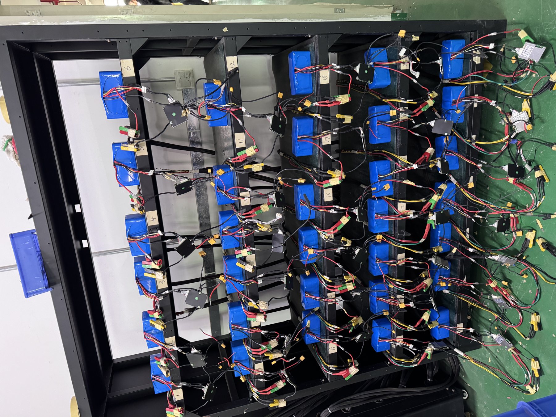
Select a vehicle and route representative of the demanding normal duty. Use the intended charger, firmware, payload, speed settings, and operating temperature envelope. Define the number of shifts or cycles needed to observe charging behavior and thermal trends. Capture the route, task count, energy use, connection time, charging current over time, alarms, and any manual intervention. The acceptance criterion should relate to the operation: completed missions and required reserve at the end of the test period.
Include a missed charge opportunity. A dock may be occupied or a vehicle may fail to align. Observe whether the fleet controller reschedules the charge, allocates another robot, or lets the vehicle continue until it stops. This exception can reveal a major availability problem even if the battery itself performs within specification. Also inspect the contact surfaces or manual connector after repeated use for wear, heat, and contamination according to the approved procedure.
For safety, pilot tests must use the site and OEM's approved methods. Do not intentionally create dangerous short circuits, overloads, or uncontrolled thermal conditions. If a required fault response cannot be safely demonstrated on a working site, use a controlled bench setup and state what remains unverified in the field. Record failures and corrective actions before volume approval. A pilot is a decision gate, not a marketing photograph.
Match procurement documents to the approved configuration
The RFQ should identify vehicle model, required pack envelope, nominal and operating voltage, load profile including peaks, usable-energy target, charger model and profile, communication interface, expected environment, mounting method, order quantity, and project schedule. Ask for a matrix of supported, conditional, excluded, and unknown requirements. If a supplier cannot answer without a vehicle drawing or log, provide that input rather than asking for an unconditional promise.
Keep the sample bill of materials connected to the production bill of materials. Record cell, BMS, enclosure, connector, firmware, harness, label, and charger revisions as applicable. The OEM should define which changes require a new bench test, a vehicle pilot, or only a document update. An alternative component can appear equivalent on paper yet change a fit, alarm threshold, or charging handshake. Revision control protects both the buyer and supplier.
Request model-specific safety and transport documents where relevant, and check that the named pack and shipment match. Do not assume that a report for a different model covers the proposed vehicle battery. Our shipping-document model match guide explains how an importer can compare the actual item with the paperwork. The logistics specialist and applicable route rules determine the final shipping process.
Define support responsibilities before scale-up
When a vehicle stops, the initial evidence may point to a pack alarm, charger issue, vehicle controller state, worn dock, or software dispatch rule. Agree who performs first-line triage and what data each party receives. A useful event record includes vehicle ID, battery serial and revision, charger ID, time, mission, payload, temperatures, BMS messages, controller logs, and safe photographs of contacts or wiring. Preserve the original event sequence.
Set a path for safety events distinct from routine performance questions. Smoke, leakage, swelling, unusual odor, or uncontrolled heating require the site's emergency procedure and qualified personnel. Remote troubleshooting must not ask an operator to open a pack, defeat protection, or ship a suspect battery without written instructions. For ordinary faults, use controlled steps and written findings before assigning responsibility. The support page describes the contact path; contractual terms control warranty decisions.
Plan spare stock, replacement training, and firmware support before the fleet grows. A small pilot can receive attention from the original engineering team; a deployed fleet needs repeatable instructions for local technicians. Record how a pack is quarantined, identified, returned to service, or replaced. If the OEM changes its charger or vehicle firmware, review battery compatibility again rather than assuming the original sample approval still applies.
Compare proposals on fleet outcomes, not a single pack price
Normalize quotations to the same mission profile and integration boundary. A less expensive pack may require more chargers, more vehicles, or more staff time if its charging workflow does not meet throughput. Another offer may include protocol mapping, custom enclosure work, pilot support, and spare-pack documentation. Show these differences explicitly. Do not infer total cost of ownership from an unsupported cycle-life slogan or a single unit price.
Ask bidders to explain the evidence behind performance and lifetime claims. A cycle figure is meaningful only with its depth of discharge, charge and discharge rates, temperature, end-of-life definition, and test method. The proposed fleet can have a different duty. Compare measured or approved data for the exact configuration and identify remaining uncertainties. Avoid invented savings percentages or claims that one chemistry always wins economically.
Keep the decision reversible during the pilot. Agree on sample quantity, test window, pass criteria, issue-resolution process, and a gate for production release. If the first sample exposes an interface gap, revise the specification and retest the changed combination. The OEM/ODM capability page provides a route for discussing pack architecture, BMS, communications, enclosure, and sample planning with YZL POWER.
Common mistakes in fleet battery selection
One mistake is choosing the largest pack that fits and assuming the vehicle will stay available longer. Extra mass can affect the vehicle; the charger may take too long to restore the larger energy reserve; and the fleet's dispatch policy may still send robots to the dock at the wrong time. Measure the mission and model the complete work and charge cycle. Size for the required operation with an approved reserve, then validate the result.
Another mistake is treating a successful charge on a bench as proof of docking performance. The bench may not include vehicle alignment, contact wear, software handshake, or a busy station. Test the actual vehicle and charger over repeated cycles. Likewise, a declared CAN or RS485 port does not prove useful fleet telemetry. Validate messages, stale-data handling, fault codes, and firmware pairing.
A third mistake is accepting a sample with undocumented differences from production. A changed enclosure, harness, BMS setting, or charger firmware can change the outcome. Freeze revisions and agree on change gates. Do not conceal a conditional result in a general claim of “AGV compatible.” Compatibility belongs to an approved vehicle and charger configuration.
FAQ
How should an OEM estimate AGV or AMR battery capacity?
Start with measured mission energy, return-to-charge reserve, expected temperature and aging, then apply the approved pack's usable-energy limits. Compare several operating scenarios and validate on a representative vehicle. Nominal amp-hours alone do not define fleet availability.
Is opportunity charging always better than swapping?
No. Opportunity charging relies on enough dwell time, charger access, and reliable docking. Swapping requires safe service time, spare inventory, and handling procedures. Compare the full workflow and throughput for the specific fleet rather than assuming one method is universally superior.
Can the fleet controller rely only on battery percentage?
It should consider data validity, voltage and current state, alarms, charger status, and the energy needed to reach a station. The exact decision logic belongs to the vehicle OEM and fleet operator. A stale percentage can mislead dispatch planning.
What evidence should a supplier provide for an RFQ?
Ask for the proposed model's electrical and mechanical limits, charging requirements, BMS interface description, revision-controlled drawing, relevant model-specific documents, and an acceptance test plan. Identify unknowns and conditions rather than treating marketing material as a specification.
What changes require a new integration test?
Changes to the battery pack, BMS firmware or thresholds, charger profile, vehicle controller software, harness or connector, mounting, or duty cycle can matter. The approved change-control plan should classify each change and specify a document review, bench test, or vehicle pilot as appropriate.
Conclusion and next action
Treat an AGV or AMR pack as one component in a fleet operating system. Define missions, charging opportunities, exceptions, communication, physical fit, and support before buying production quantity. Then witness a representative vehicle pilot and keep its approved revisions with the order. For a project-specific battery discussion, send the vehicle drawing, duty log, charger details, and fleet availability target to YZL POWER's industrial battery team or email [email protected]. A clear input package helps the engineering review focus on the interfaces that determine whether the fleet can actually run.