A telecom backup battery should be selected from a defined outage, the loads that must remain online, and evidence of how the complete system behaves. A nominal amp-hour figure is not a runtime promise. The buyer needs a measured or clearly qualified load profile, a stated usable battery window, an electrical interface review, and a field acceptance test with an agreed endpoint. This article provides a practical framework for building that evidence before approving a site rollout.
The framework describes general engineering and procurement practice. It does not specify a YZL POWER model, certify a site design, or promise any particular duration. YZL POWER's source materials include 48V telecom and UPS backup directions, BMS integration and communication options. Final electrical limits, documentation and application suitability must be checked for the exact model, controller and destination.
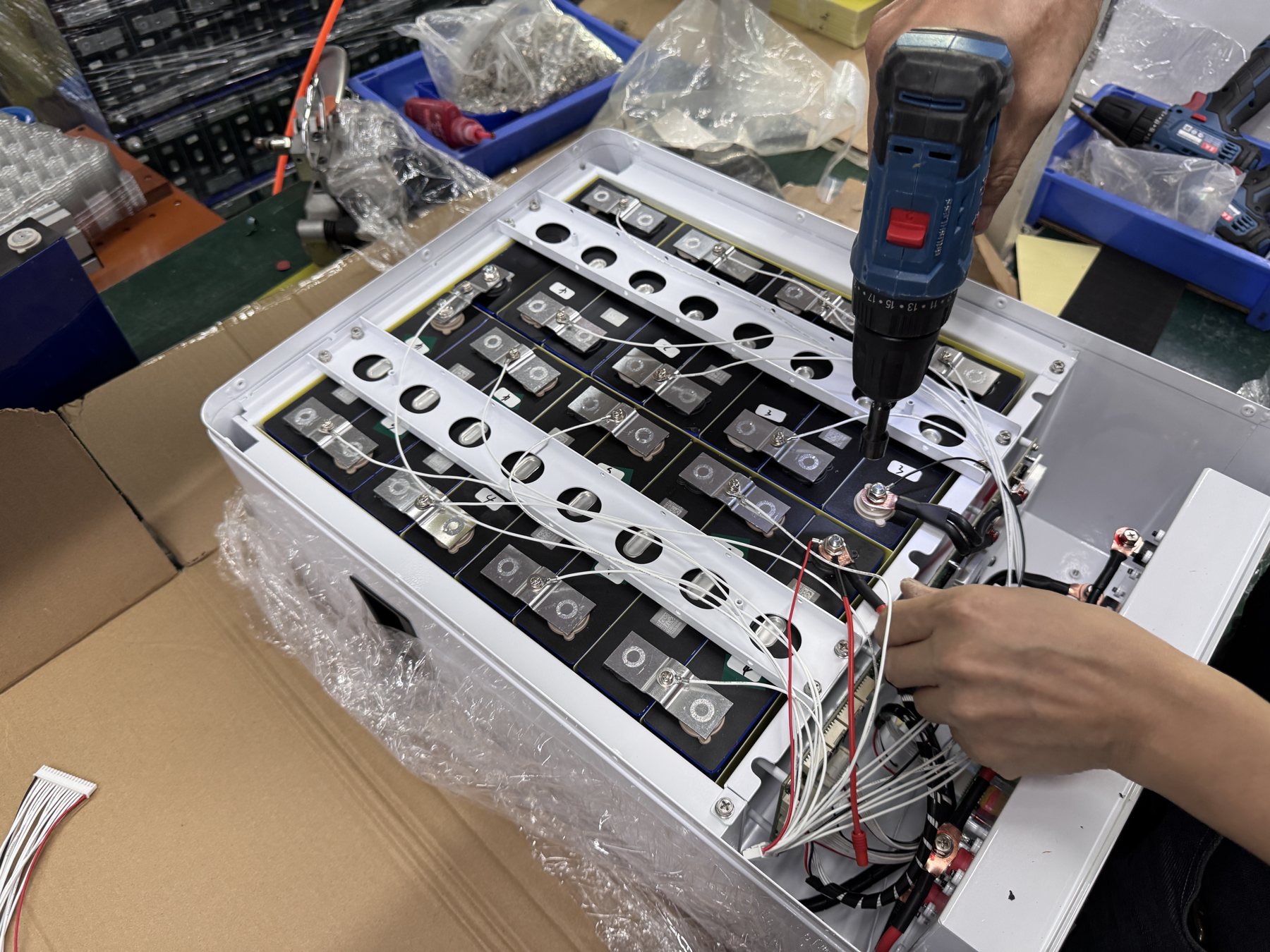
Write an autonomy requirement that can actually be tested
“Four hours of backup” leaves critical questions unanswered. Does the clock begin when grid input fails, when the rectifier stops supplying the bus, or when a generator fails to start? Which radio, transmission, monitoring and cooling loads remain connected? Is the requirement for a new battery at commissioning or for a later point in service? What initial state of charge may the operator assume? The project team should resolve those questions in a short signed requirement before comparing quotations. Otherwise, different suppliers can return apparently comparable runtimes that represent different boundaries.
Define the outage scenario and the operating mode separately. A site may need to bridge generator starting, survive an extended grid interruption, or cycle daily with a solar input. These duties place different demands on recharge availability and energy reserve. State the equipment that is essential, the loads that may be shed, the allowed order of shedding, and the conditions under which a reduced service mode is acceptable. A cabinet fan may be essential even if it is not a communications load; a separate air-conditioning circuit might not be powered by the battery at all. Draw the boundary rather than assume it.
The written requirement should name the site type, controller revision, initiating event, supported loads, duration, ambient conditions, initial battery condition, endpoint and acceptance method. Include the person authorized to approve a change. An endpoint can be a stated reserve, a controller action or the completion of the required interval, but it must be the same endpoint used in the calculation and test. If “backup time” is left undefined, a successful laboratory discharge can still fail the operator's real objective.
Separate a service target from a battery label
A service target answers what must remain available to users. A battery label states a product rating under defined conditions. The two meet only after the power path, host cutoff, losses and usable energy are analyzed. Treat a preliminary capacity estimate as an input to engineering, not as proof. A clear autonomy statement also makes procurement fair: every bidder can work from the same load list and environmental assumption, and any exception appears next to the proposed model.
Measure the load at the relevant electrical boundary
Build a site inventory, then collect the current or power seen by the battery-supported bus during representative operation. Nameplates help identify equipment and maximum ratings, but they may not describe normal consumption or changes with radio traffic, fan speed, cabinet heating and auxiliary equipment. Log enough operating time to capture the modes that matter to the outage case. Keep timestamps, the meter location, bus voltage and relevant site conditions. If measurement is impossible before a first quotation, identify the assumed values and plan to confirm them during commissioning.
Average power largely determines energy demand; short current peaks can determine whether the BMS, fuse, cable and host remain connected. Record both the typical time profile and the magnitude and duration of credible peaks. Do not size energy solely from a momentary peak, but do not ignore that peak because it contributes little energy. The highest simultaneous load combination may also be different from the sum of every device's nameplate maximum. A trace from the real site, interpreted by the site engineer, is more useful than either extreme.
Mark the measurement boundary on a simple single-line diagram. If the load is measured on the supported DC bus, applying rectifier efficiency again may double count a loss. If an AC load is served through an inverter, its conversion losses should be included. If a control unit remains active throughout an outage, its consumption belongs in the profile. The supplier should be able to trace every watt in the calculation to a measured point or a documented assumption.
A load register can have columns for equipment, operating state, measured or estimated power, duty interval, source of evidence and owner. Use a separate column for items that are excluded from battery support. This distinction catches an expensive misunderstanding: an operator may believe a cooling subsystem is included while a supplier's worksheet excludes it. It also highlights changes after a network upgrade, when a new radio or transmission device increases demand without any change to the battery.
Calculate energy without hiding the assumptions
At its simplest, required load energy is the sum of power multiplied by time over the outage. For a constant illustrative 2 kW load over four hours, the load-side energy is 8 kWh. That is a classroom example, not a YZL POWER product rating or a typical site load. Real sites have changing demand, so divide the outage into intervals and sum each interval's energy. Use the same measurement point throughout the worksheet and include any transition that materially changes the result.
The energy required by the loads is not necessarily the pack's nominal stored energy. The host may disconnect before the BMS does; an operator may require a reserve; temperature, conversion losses and service-life allowances may reduce the energy that can be relied upon. Write each allowance in its own row, identify its source and check for overlap. Multiplying several unexplained “safety factors” creates a design that is difficult to audit and may still miss the actual weak point. A measured site profile plus model-specific usable-energy data is a stronger basis.
For a second illustrative case, suppose the essential DC load averages 1.5 kW for three hours and another 0.5 kW of intermittent equipment operates for one of those hours. The load-side total is 5.0 kWh. The project team must then compare that demand with the exact pack's approved usable energy at the intended current, temperature and cutoff, and account for losses between the measurement point and the battery. The arithmetic is simple; defining valid inputs is the difficult part.
Ask a bidder to return the worksheet with the measured trace attached, not only a selected Ah rating. If the proposed design includes multiple modules, show the permitted configuration and how usable energy is allocated. If the calculation changes after a load survey, the revision should explain why. The objective is not to find a universally “correct margin.” It is to establish a traceable decision that the owner can revisit when the site or equipment changes.
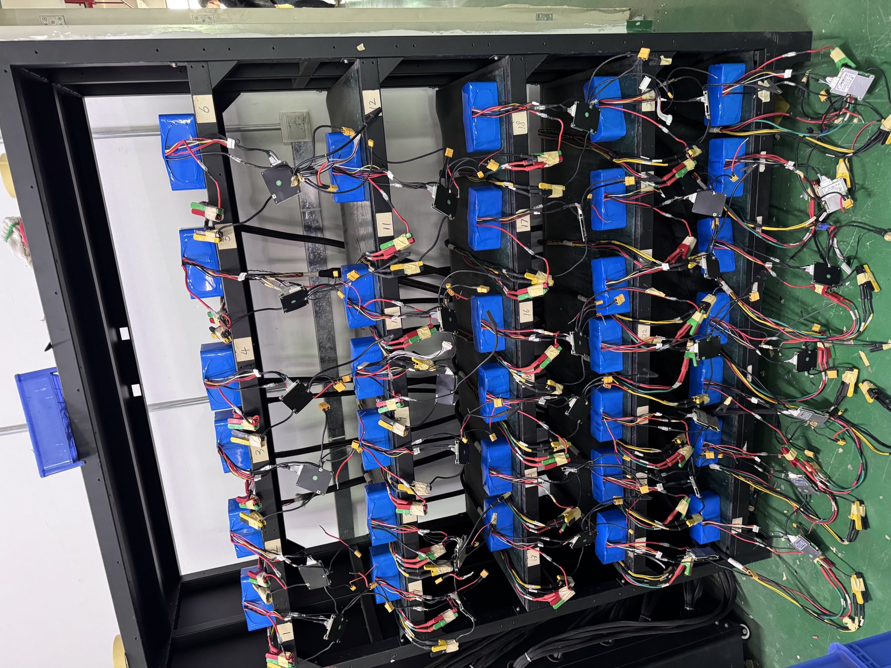
Check the voltage window and host response
A nominal “48V” description is a system class, not a complete electrical interface. Obtain the rectifier settings, supported bus range, low-voltage disconnect setting, alarm thresholds and equipment input limits. Compare them with the exact battery's permitted charge and discharge range. The controller may shut down before the pack reaches its own limit, reducing available runtime. Alternatively, the BMS may open first and cause a different alarm sequence. The site operator needs to know which behavior is expected before an outage occurs.
Review state-of-charge reporting as well as electrical limits. A voltage-based gauge calibrated for a different chemistry can produce misleading remaining-time estimates. If the host communicates with the battery, obtain the protocol specification, message mapping, firmware versions, physical connector and pinout. If no digital communication is used, define the alternative alarm and monitoring arrangement. A matching plug shape is not proof of protocol compatibility. The existing system compatibility note explains why voltage alone cannot settle this question.
Record the event visible to operations staff when charge is low, the battery is hot, communication is lost or a module disconnects. Does the network management system receive a clear alarm? Is the event timestamped and retained after a controller restart? Is there sufficient warning for a technician to act? A battery can pass a standalone discharge while the site fails the service objective because an alarm never reaches the team that dispatches support.
Verify recharge after the outage
Autonomy is only half of site resilience. Once an outage ends, the battery must recover before another event. Determine the charging power available after normal site loads are served, the pack's approved charging current, and the rectifier's control mode. A powerful charger does not guarantee quick recovery when the active site load takes priority or the BMS limits charging under particular conditions. State the required recovery time as a separate acceptance item rather than burying it in the autonomy figure.
If a generator is part of the architecture, review its start and transfer sequence with the rectifier. Check the mode changes, alarm behavior and the stability of the power path when the generator is loaded. A solar or hybrid installation needs a time-based model: sunlight may be poor during the same weather event that caused an outage. Do not count on a fixed daily photovoltaic contribution without site-specific evidence. The test plan should cover transitions among grid, generator, renewable input and battery where those modes are present.
Frequent cycling creates a different project from rare standby use. Record the expected number of events, depth of discharge and recharge windows as operating assumptions, then seek model-specific data. Do not convert generic chemistry claims into a promised service life. If the contract includes a future runtime requirement, specify the conditions and verification method at that point. The sizing reserve should connect to that requirement.
Treat cabinet conditions as part of the battery design
The battery may sit in a sheltered room, a ventilated shelter or a sealed outdoor cabinet near rectifiers and radio equipment. Measure or estimate the temperature at the battery position during hot operation, cold start and loss of cabinet cooling. Charging and discharging limits may differ. The exact pack and control strategy must be approved for the relevant conditions; a broad chemistry label cannot substitute for a model-specific operating specification.
Check physical fit with more than width, height and depth. The review should cover rack loading, lifting route, module handling points, cable entry, bending clearance, service access, labels, fuse or breaker reach and the ability to remove one module without disturbing others. If several modules connect to a common bus, the installer needs an approved wiring arrangement and protection scheme. A mock installation or site drawing can expose problems that a product photograph cannot.
Environmental language should also be specific. “Outdoor compatible” can mean an exposed enclosure or a battery protected by a separate cabinet. Describe dust, water, vibration and the cabinet's role; then ask for the exact assembly's evidence. A pack may be acceptable inside an appropriately designed cabinet without having the same rating as a directly exposed unit. The site engineer should approve this boundary.
Plan protection, isolation and maintainability
Map credible failures before approving the architecture. What happens if one module alarms, a fuse opens, a BMS disconnects, a sensor fails or a communication cable is damaged? What does the host display, and can the site remain in the agreed reduced mode? A parallel arrangement may increase capacity or resilience only when the modules, control logic, protection and cabling are designed for that configuration. Do not parallel arbitrary packs because their labels show the same nominal voltage.
Request a single-line diagram for the final design. It should identify the battery, disconnect points, protective devices, supported bus, rectifier, monitoring links and grounding arrangement as applicable. Ratings and revision identifiers matter. The diagram should distinguish a normal operating path from an emergency isolation path. Installation and service personnel need an approved procedure for making the system safe before touching conductors or connectors.
Operations should have a response for each significant alarm. Identify who receives it, the permitted remote checks, the condition that requires a site visit and the evidence needed before return to service. If the site can continue with one string isolated, that mode must be designed and tested. If it cannot, the dispatch process should say so. A design that looks robust on a schematic can still be fragile when a technician cannot identify a failed module or obtain a safe replacement.
Run a field acceptance test that reflects the quotation
Before the test, freeze the installed model, BMS and host firmware, controller settings, initial state of charge, load state and ambient conditions. Agree on the initiating event and the endpoint. Capture bus voltage, current, temperature, alarm events, communication state and the operating status of each essential load. A witnessed result without a test condition is difficult to compare with a supplier's calculation or a later site.
Use a load representative of the contractual requirement. A reduced weekend load may make autonomy look impressive while providing little evidence for the working site. Where a full discharge creates unacceptable operational risk, the owner can approve a controlled partial test combined with model-specific discharge data. Record exactly what was observed and what was inferred. Do not label a partial demonstration as a witnessed full-duration result.
Continue the test through recovery. Confirm that the rectifier returns to the intended charging mode, the BMS permits charging under the observed conditions, and alarms clear or remain latched as specified. Check that the network management system retains the outage record. If a firmware or threshold change is made during the test, document it and repeat the affected steps. The industrial battery pilot validation plan explains how to control these revisions before a larger release.

Compare supplier proposals on evidence, not on Ah alone
Give each bidder the same RFQ packet: supported-load inventory, measurements or assumptions, backup target, environmental profile, rectifier and controller models with firmware, communication requirements, rack space, module handling constraints, intended market and requested documents. If the project replaces lead-acid strings, include the current wiring and charging settings. A supplier should identify unresolved inputs rather than silently assume the easiest scenario.
Ask for a response that states the proposed model and revision, electrical operating window, usable-energy basis, current limits, mechanical drawing, communication behavior, protection response, calculation worksheet, acceptance procedure and exceptions. List documentation by the exact model and market. A quotation containing only volts, amp-hours and unit price cannot be judged fairly against a proposal that carries the engineering work.
Keep assumptions beside the quoted configuration. If a bidder excludes cabinet cooling, assumes a new rectifier, or needs a host firmware update, that changes the project scope. Price, logistics and lead time should be evaluated after those differences are visible. For related product scope, review the UPS and telecom battery direction and the engineering capability page.
Mistakes that distort autonomy decisions
Dividing nominal watt-hours by average power and calling the result “guaranteed hours” is the most common shortcut. It can ignore the host cutoff, permitted usable window, temperature and losses. Another shortcut is mixing measurements taken at different electrical points. A third is using a short laboratory discharge of one new sample as evidence for every cabinet, climate and service age. Each problem has the same remedy: write down the boundary, conditions and data source.
Another error is overlooking operational integration. A battery may fit the rack while the existing monitoring system interprets its state of charge incorrectly or fails to pass a protection alarm upstream. Include the rectifier, controller and network management configuration in the change record. Avoid the opposite error of adding several arbitrary margins because measurement is inconvenient. If load uncertainty is large, a site survey is usually more informative than a very large unexplained allowance.
Finally, do not accept an undocumented field test. State the witness, load condition, initial state, endpoint, observations, pass criteria and corrective-action route before technicians arrive. If an issue occurs, preserve logs and configuration details rather than adjust parameters until the problem disappears. A repeatable test supports both a procurement decision and later troubleshooting.
Frequently asked questions
Can the supplier guarantee runtime from an amp-hour rating?
No. Runtime depends on load, usable energy, current, temperature, controller cutoff and power-path losses. Model-specific data under stated conditions can support an estimate, but the site should verify the integrated result against the approved requirement.
Should a brief high-current peak be included?
Record its magnitude and duration. It may contribute little total energy, but it can trip protection or cause a voltage drop. Check peak-current compatibility separately from total energy sizing, then include the peak's energy if it materially changes the profile.
Is an existing 48V rectifier automatically compatible?
No. Compare the exact charge settings and voltage window, current limits, communication interface and alarm behavior. The host model and firmware matter. A controlled integration test is sensible where written evidence is incomplete.
What if the operator cannot perform a full discharge test?
Agree on a safer partial test and supporting calculation with the site owner. Clearly state which results were measured and which were inferred. Keep the residual uncertainty visible in the acceptance record.
When should the autonomy worksheet be revised?
Update it when loads, operating modes, controller settings, battery configuration, cabinet environment or service targets change. Keep the previous revision with the site configuration history so a later engineer can understand why the installed capacity was selected.
Decision and next step
A defensible telecom backup purchase begins with a testable outage definition, measured or qualified load data, a transparent energy calculation, verified host compatibility, a physical site review and a witnessed acceptance plan. The output is an agreement about what stays online, for how long, under which conditions and how the claim will be proven. It is more useful than a nameplate capacity presented without a system boundary.
Send the rectifier and controller models, supported-load log, rack drawings, autonomy target, site temperature range and destination to [email protected] or WhatsApp +86 138 0280 9405. YZL POWER can review the application and discuss a model-specific configuration and test plan. The final proposal should list assumptions and evidence before a sample is ordered.